January 2007 197
Intel
®
855GME Chipset and Intel
®
6300ESB ICH Embedded Platform Design Guide
Intel
®
6300ESB Design Guidelines
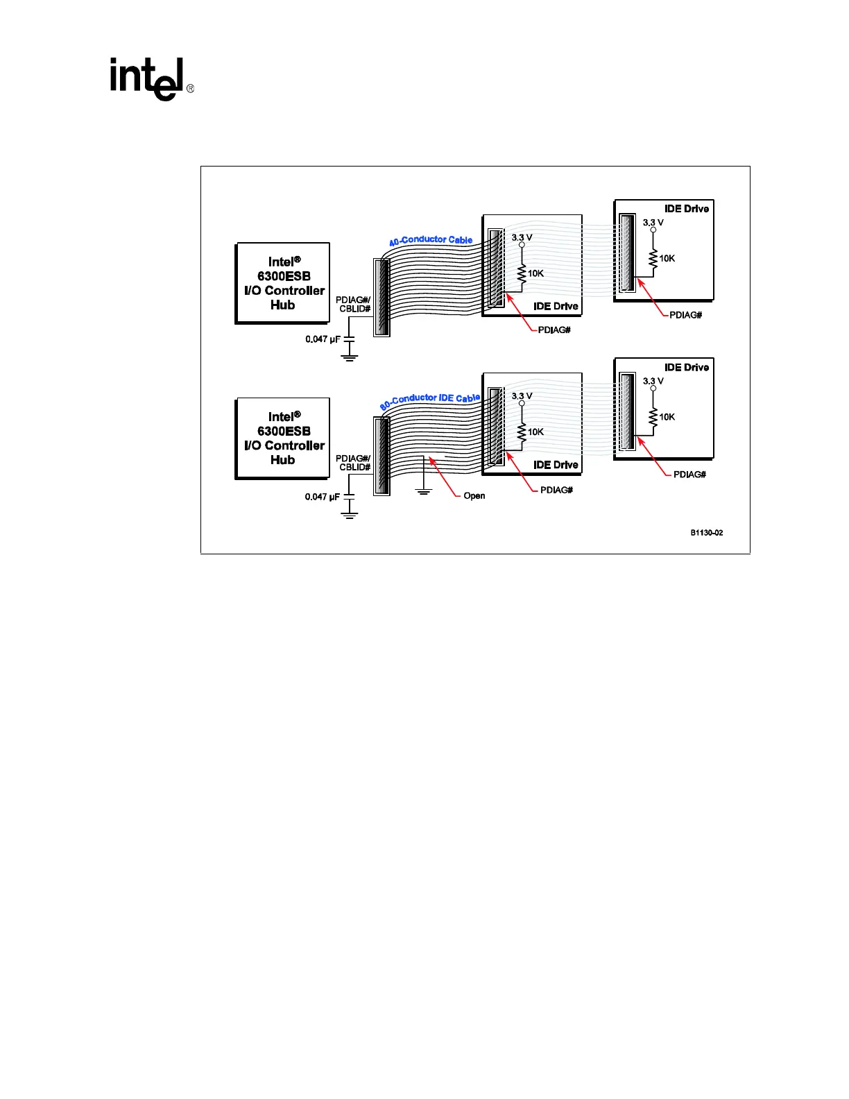
This mechanism creates a resistor-capacitor (RC) time constant. Hard drives supporting Ultra
DMA modes greater than two (Ultra DMA/33) drive PDIAG#/CBLID# low and then release it
(pulled up through a 10 K
Ω resistor). The drive samples the signal after releasing it. In an
80-conductor cable, PDIAG#/CBLID# is not connected through to the host and therefore the
capacitor has no effect. In a 40-conductor cable, the signal is connected to the host. Therefore, the
signal rises slower as the capacitor charges. The drive may detect the difference in rise times and it
reports the cable type to the BIOS when it sends the IDENTIFY_DEVICE packet during system
boot as described in the
ATA/ATAPI-6 Standard.
Figure 96. Device Side IDE Cable Detection