January 2007 199
Intel
®
855GME Chipset and Intel
®
6300ESB ICH Embedded Platform Design Guide
Intel
®
6300ESB Design Guidelines
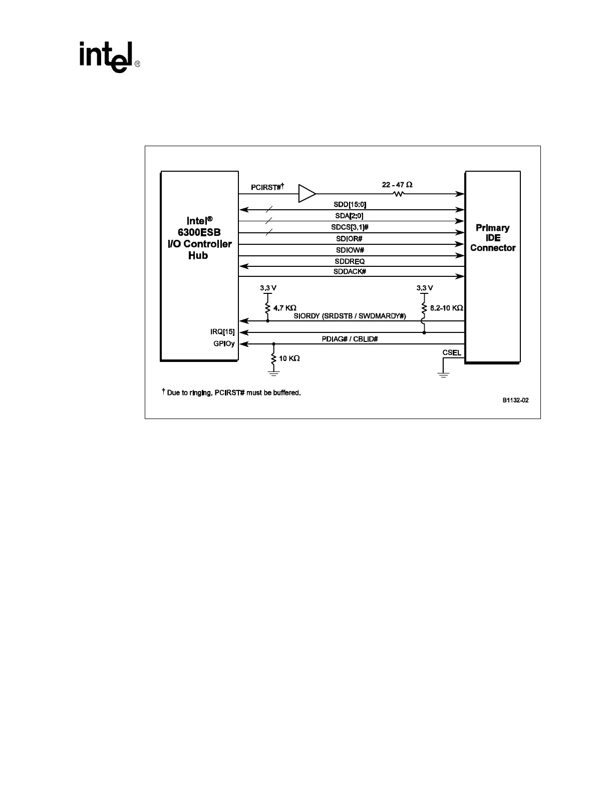
9.3.4 Secondary IDE Connector Requirements
• 22 Ω - 47 Ω series resistors are required on PCIRST#. The correct value should be determined
for each unique motherboard design, based on signal quality.
• An 8.2 KΩ to 10 KΩ pull-up resistor is required on IRQ15 to V
CC
3.3.
• A 4.7 KΩ pull-up resistor to V
CC
3.3 is required on SIORDY.
• Series resistors are not required but may be placed on the control and data line to improve
signal quality. Place the resistors as close to the connector as possible. Resistor values are from
33
Ω - 47 Ω.
• The 10 KΩ resistor to ground on the PDIAG#/CBLID# signal is required on the Secondary
Connector. This change is to prevent the GPI pin from floating when a device is not present on
the IDE interface.
• Place all resistors as close to the IDE connector as possible.
Figure 98. Connection Requirements for Secondary IDE Connector