January 2007 59
Intel
®
855GME Chipset and Intel
®
6300ESB ICH Embedded Platform Design Guide
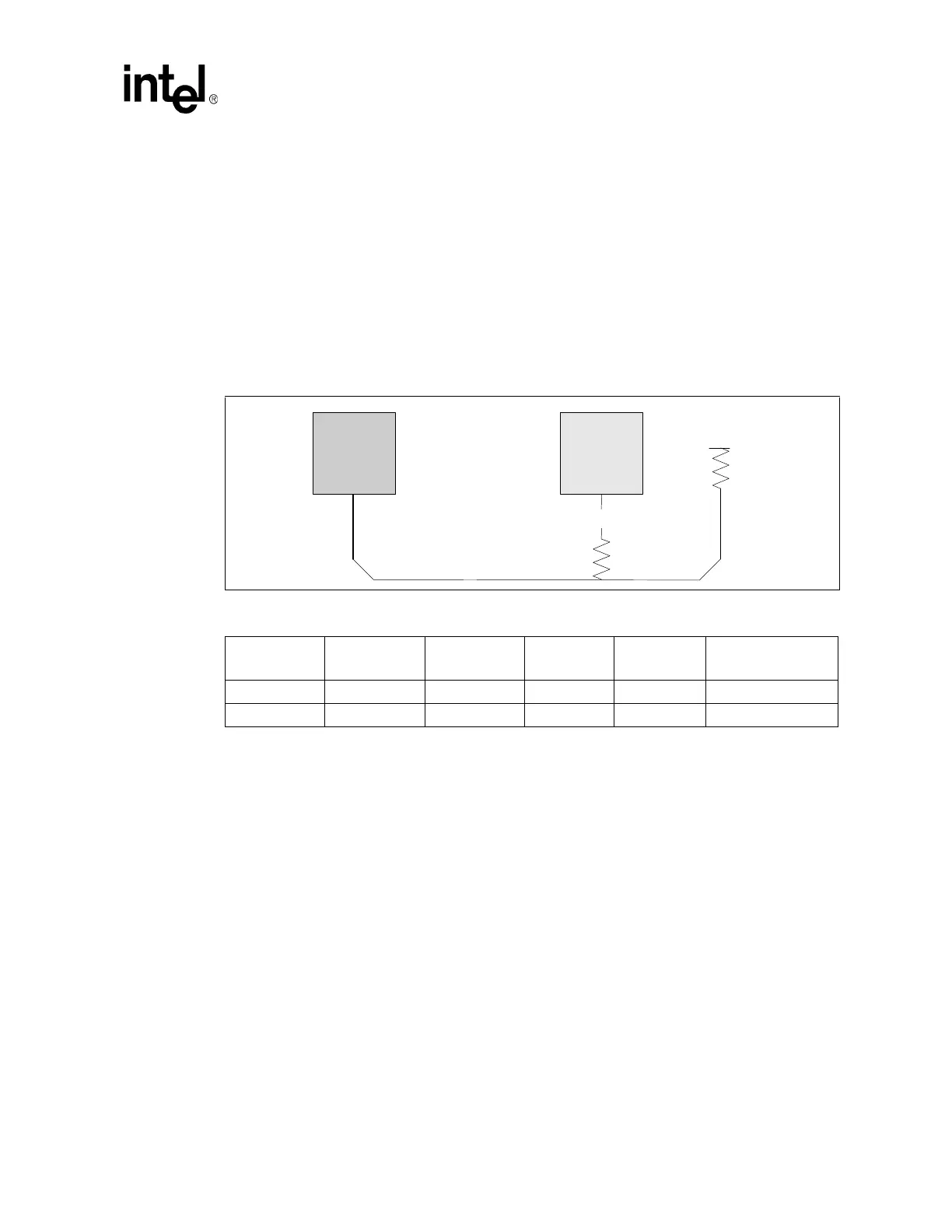
4.1.5.1 Topology 1A: Open Drain (OD) Signals Driven by the Intel
Pentium M/Celeron M Processor – IERR#
The Topology 1A OD signal IERR# shall adhere to the following routing and layout
recommendations. Table 11 lists the recommended routing requirements for the IERR# signal of
the Intel Pentium M/Celeron M processor. The routing guidelines allow the signal to be routed as
either micro-strip or strip-lines using 55 Ω ± 15% characteristic trace impedance. Series resistor R1
is a dampening resistor for reducing overshoot/undershoot reflections on the transmission line. The
pull-up voltage for termination resistor Rtt is VCCP (1.05 V). Due to the dependencies on system
design implementation, IERR# may be implemented in a number of ways to meet design goals.
IERR# may be routed as a test point or to any optional system receiver. Figure 16 depicts the
routing illustration for Topology 1A.
4.1.5.2 Topology 1B: Open Drain (OD) Signals Driven by the Intel
Pentium M/Celeron M Processor – FERR# and THERMTRIP#
The Topology 1B OD signals FERR# and THERMTRIP# shall adhere to the following routing and
layout recommendations. Table 12 lists the recommended routing requirements for the FERR# and
THERMTRIP# signals of the Intel Pentium M/Celeron M processor. The routing guidelines allow
the signals to be routed as either micro-strips or strip-lines using 55 Ω ± 15 percent characteristic
trace impedance. Series resistor R1 is a dampening resistor for reducing overshoot/undershoot
reflections on the transmission line. The pull-up voltage for termination resistor Rtt is VCCP
(1.05 V).
Intel recommends that the FERR# signal of the Intel Pentium M/Celeron M processor be routed to
the FERR# signal of the Intel
®
6300ESB. THERMTRIP# may be implemented in a number of
ways to meet design goals. It may be routed to the 6300ESB or any optional system receiver. It is
recommended that the THERMTRIP# signal of the Intel Pentium M/Celeron M processor be
routed to the THERMTRIP# signal of the 6300ESB. The 6300ESB’s THERMTRIP# signal is a
new signal to the I/O controller hub architecture that allows the 6300ESB to quickly put the whole
system into a S5 state whenever the catastrophic thermal trip point has been reached.
Figure 16. Routing Illustration for Topology 1A
Table 11. Layout Recommendations for Topology 1A
L1 L2 L3 R1 Rtt
Transmission Line
Type
0.5” – 12.0” 0” – 3.0” 0” – 3.0” 56 Ω ±5% 56Ω ± 5% Micro-strip
0.5” – 12.0” 0” – 3.0” 0” – 3.0” 56
Ω ±5% 56Ω ±5% Strip-line
L2
VCCP
L3
Rt
L1
CPU
System
Receiver
R1