196
Intel
®
855GME Chipset and Intel
®
6300ESB ICH Embedded Platform Design Guide
Intel
®
6300ESB Design Guidelines
This mechanism allows the BIOS, after diagnostics, to sample PDIAG#/CBLID#. When the signal
is high, there is 40-conductor cable in the system and Ultra DMA modes greater than two (Ultra
ATA/33) must not be enabled.
When PDIAG#/CBLID# is detected low, there may be an 80-conductor cable in the system, or
there may be a 40-conductor cable and a legacy slave device (Device 1) that does not release the
PDIAG#/CBLID# signal as required by the
ATA/ATAPI-6 standard. In this case, BIOS should
check the IDENTIFY DEVICE information in a connected device that supports Ultra DMA modes
higher than two. When ID Word 93, bit 13 is a one, an 80-conductor cable is present. When this bit
is zero, a legacy slave (Device 1) is preventing proper cable detection and BIOS should configure
the system as though a 40-conductor cable is present, and notify the user of the problem.
9.3.2 Device-Side Cable Detection
For platforms that must implement Device-Side detection only (e.g., NLX platforms), a 0.047 µF
capacitor is required on the motherboard as shown in Figure 96. This capacitor should not be
populated when implementing the recommended combination Host-Side/Device-Side cable
detection mechanism described above. Please note some drives may not support device-side cable
detection.
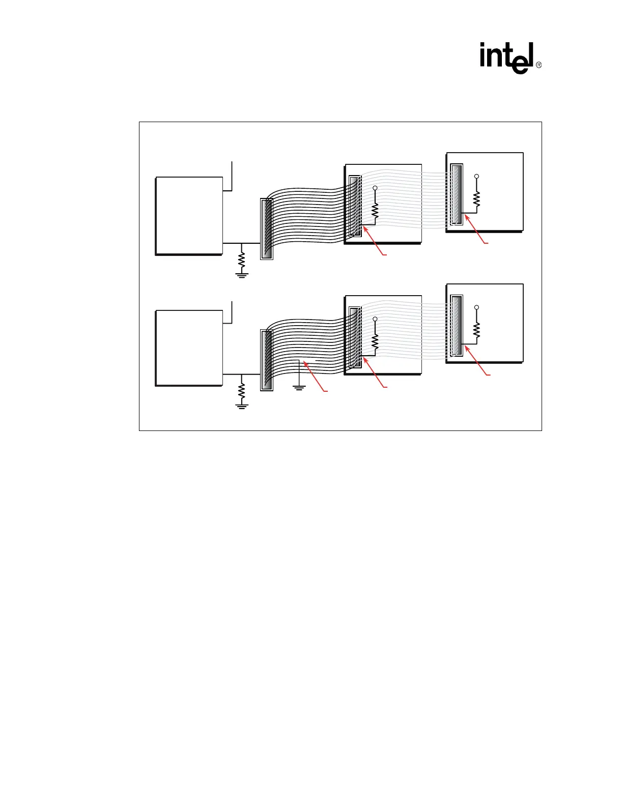
Figure 95. Combination Host-Side/Device-Side IDE Cable Detection
B1129-02
IDE Drive
10K
PDIAG#
3.3 V
Intel
®
6300ESB I/O
Controller Hub
Intel
6300ESB I/O
Controller Hub
GPIO
GPIO
To Secondary
IDE Connector
PDIAG#/
CBLID#
10K
4
0
-
C
o
n
d
u
c
t
o
r
C
a
b
l
e
IDE Drive
10K
PDIAG#
3.3 V
IDE Drive
10K
PDIAG#
3.3 V
GPIO
GPIO
To Secondary
IDE Connector
PDIAG#/
CBLID#
10K
8
0
-
C
o
n
d
u
c
t
o
r
I
D
E
C
a
b
l
e
IDE Drive
10K
PDIAG#
Open
3.3 V