January 2007 209
Intel
®
855GME Chipset and Intel
®
6300ESB ICH Embedded Platform Design Guide
Intel
®
6300ESB Design Guidelines
9.5.2 CNR Routing Summary
Table 81 represents a summary of the various interfaces routing requirements to the CNR Riser.
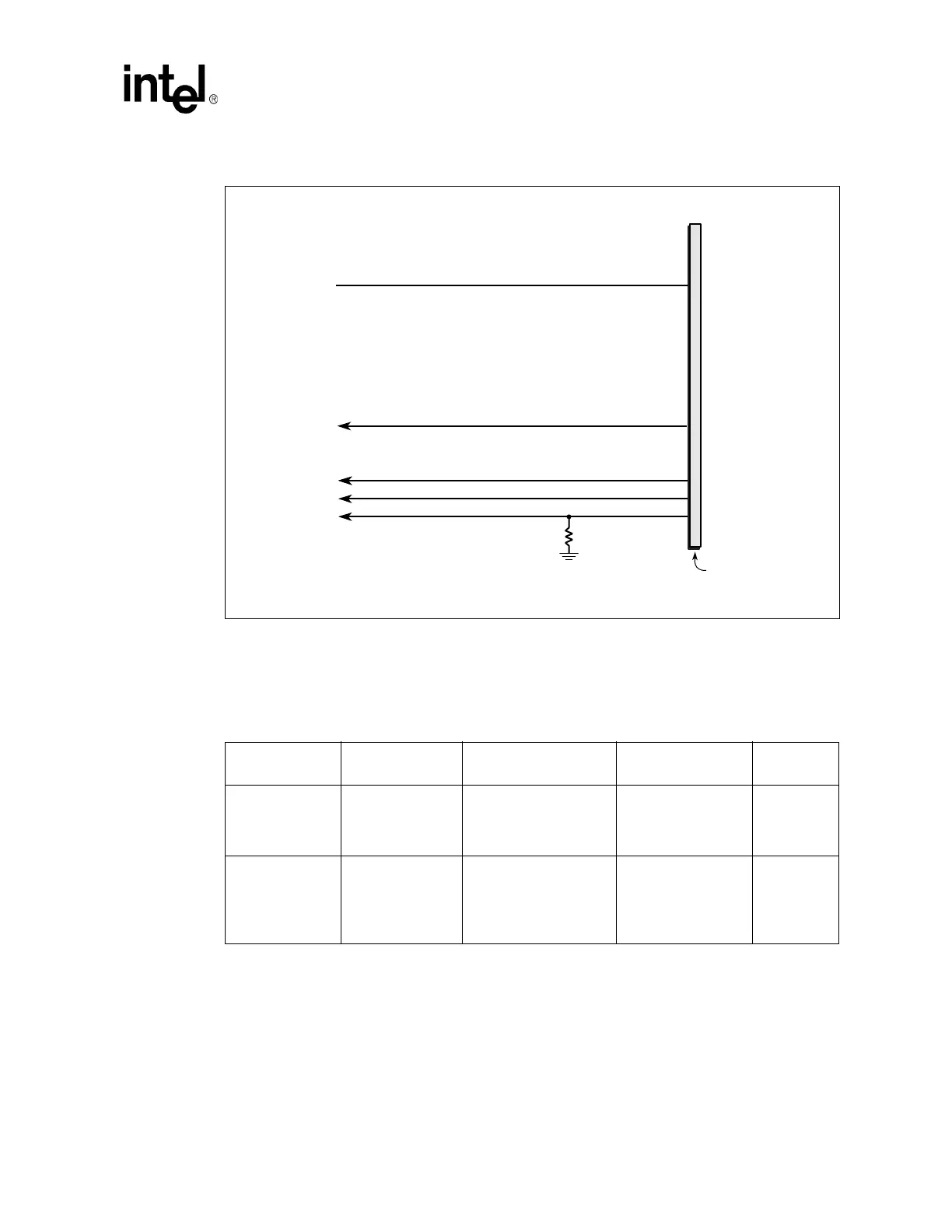
Figure 106. Motherboard AC’97 CNR Implementation without Codec Down On Board
B1158-02
AC_RST#
CDC_DN_ENAB#
Motherboard
(CNR 1.2 Compliant)
To GPIO
AC_SDIN0
AC_SDIN1
AC_SDIN2
R = 10K
CNR Connector
From Intel
®
6300ESB
I/O Cntrlr
Hub
To
Intel
6300ESB
I/O Cntrlr
Hub
Table 81. CNR Routing Summary
Trace Impedance
CNR Routing
Requirements
Maximum Trace Length
to CNR connector
Signal Length
Matching
Signal
Referencing
90
Ω Differential
USB (7.5 on 7.5)
(See
Section 9.6.1.6 for
more details)
10 inches
No more than 150 mils
trace mismatch.
Ground
55
Ω ± 10% AC’97 (5 on 10)
AC_BIT_CLK
(See Ta b l e 7 6 )
AC_SDOUT
(See Ta b l e 7 7 )
AC_SDIN (See Ta b l e 7 8 )
N/A Ground