January 2007 241
Intel
®
855GME Chipset and Intel
®
6300ESB ICH Embedded Platform Design Guide
Intel
®
6300ESB Design Guidelines
NOTE: The recommended value for R1 depends on the Processor used in the system. See the Processor
design guidelines for more info.
.
9.13.5 FWH V
PP
Design Guidelines
The V
PP
pin on the FWH is used for programming the flash cells. The FWH supports V
PP
of 3.3 V
or 12 V. When V
PP
is 12 V, the flash cells programs about 50% faster than at 3.3 V. However, the
FWH only supports 12 V V
PP
for 80 hours (3.3 V on Vpp does not affect the life of the device).
The 12 V V
PP
would be useful in a programmer environment, which is typically an event that
occurs very infrequently (much less than 80 hours). The V
PP
pin MUST be tied to 3.3 V on the
motherboard. (See Figure 134.)
Figure 132. FWH/CPU UP Signal Topology Solution
B1187-02
R1
L1
L2 L3
V
CC
CPU
Processor
Voltage
Translator
FWH
Intel
®
6300ESB
I/O Controller
Hub
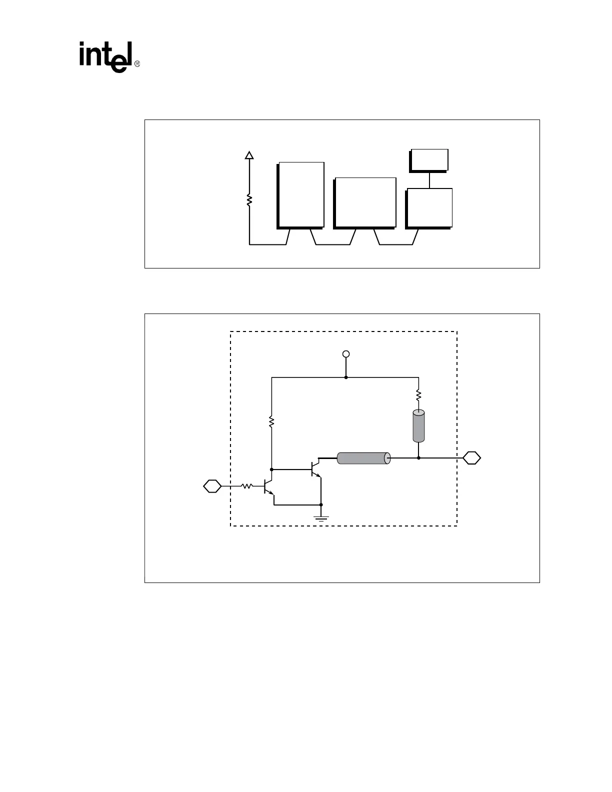
Figure 133. FWH Level Translation Circuitry
B1190-02
T1
V
CC
_of_Receiver
T2
3904
3904
300
Ω
± 5%
300
Ω
± 5%
2 K
Ω
± 5%
To_Receiver
T1 = 10" max
T2 = 3" max
Note: This transition circuit is optimized to function with the low voltage processors the Intel
®
6300ESB
ICH supports.
From_Driver