January 2007 309
Intel
®
855GME Chipset and Intel
®
6300ESB ICH Embedded Platform Design Guide
Layout Checklist
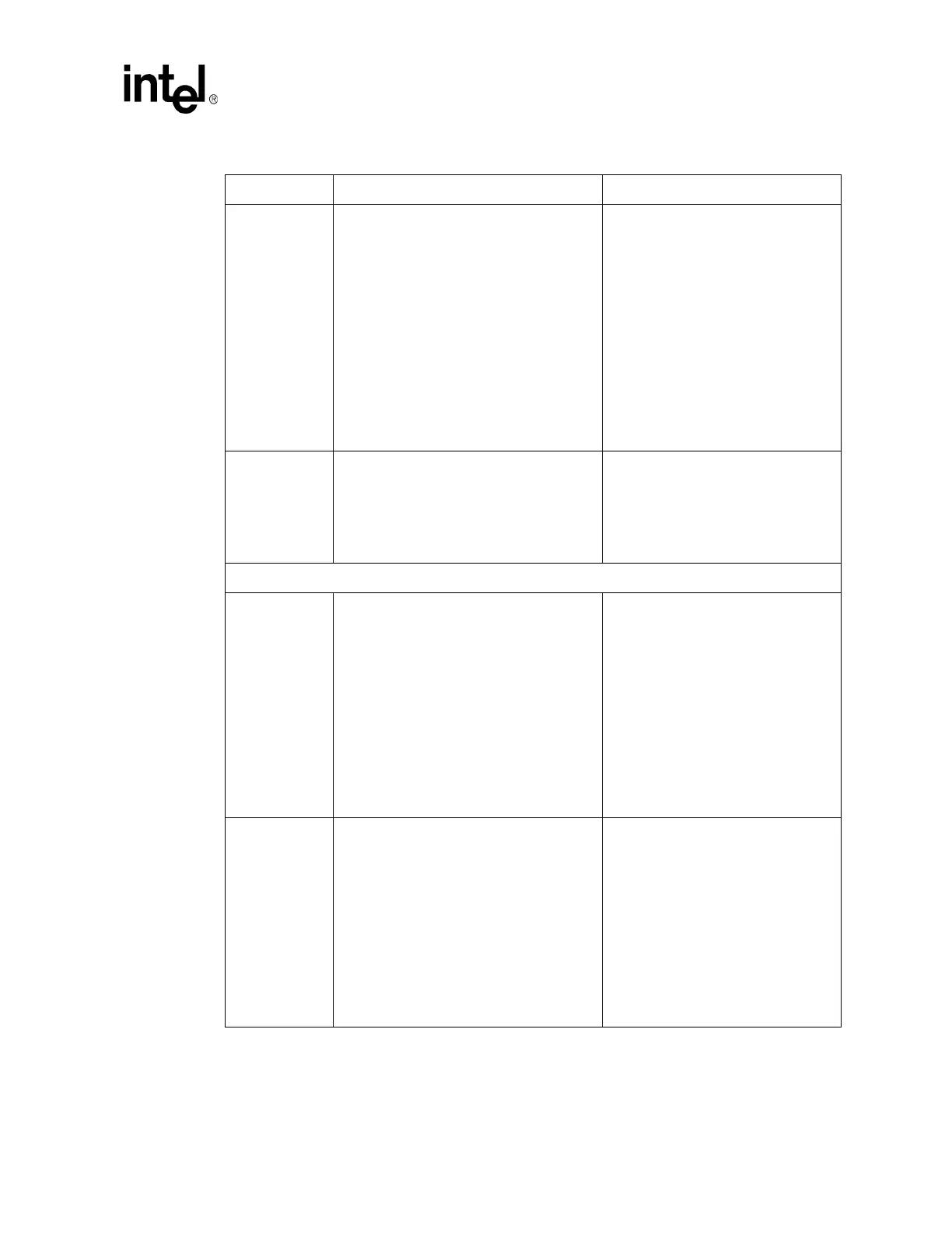
SMA[5,4,2,1]
SMAB[5,4,2,1]
• See a detailed discussion on this topic in
Section 5.4.7.
• Route with trace impedance 55
Ω ± 15%
using 2:1 spacing.
• Isolation from non-DDR signals should be
20 mils.
• GMCH pad to DIMM trace length limits are
2 to 6 inches.
• Place parallel termination resistor within 2
inches of the DIMM pad.
• Overall min/max length to the DIMM must
comply with clock length matching
requirements.
• Maximum recommended via count per
signal is 3.
• Refer to the detailed routing
guidelines in Section 5.4.7.
RCVENIN#
RCVENOUT#
• Internally shunted on Intel 855GME
chipset - no external connection
necessary.
• Recommendation is that both signals be
transitioned to the secondary side with
vias next to the package balls to facilitate
probing.
• Refer to the detailed routing
guidelines in Section 5.4.8.
DDR System Memory Decoupling
GMCH VCCSM
Decoupling
• Requires a minimum of (11) 0603, 0.1 µF
caps placed within 150 mils of the GMCH
package.
• Distribute evenly along the DDR memory
interface, placed perpendicular to the
GMCH with the power side of the caps
facing the GMCH.
• Each GMCH ground and VCCSM power
ball should have its own via.
• Each via should be as close to the
associated cap pad as possible, within 25
mils and with as thick a trace as possible.
• Two 150
μF caps between GMCH and 1st
DIMM.
• Refer to Section 4.8.1.1 for more
information.
DDR VDD
Bypass Caps
• Place 9 evenly spaced 0.1 µF 0603 caps
between the DIMMs.
• A wide trace from each cap should
connect to a via that transitions to the
ground plane layer.
• A wide trace should connect the 2.5 V side
of each cap to a via that transitions to the
2.5 V plane, each via placed as close to
the cap pad as possible.
• Each cap should also connect to the
closest 2.5 V DIMM pin on either DIMM
connector with a wide trace.
• Four 100 - 150
μF caps near the DIMMs.
• Helps minimize return path
discontinuities.
• Refer to Section 4.8.1.2 for more
information.
Table 149. Intel
®
855GME Chipset GMCH Layout Checklist (Sheet 3 of 6)
Checklist Items Recommendations Comments