Measuring Functions
Measure object on the cross-section
133
Measure object on the cross-section
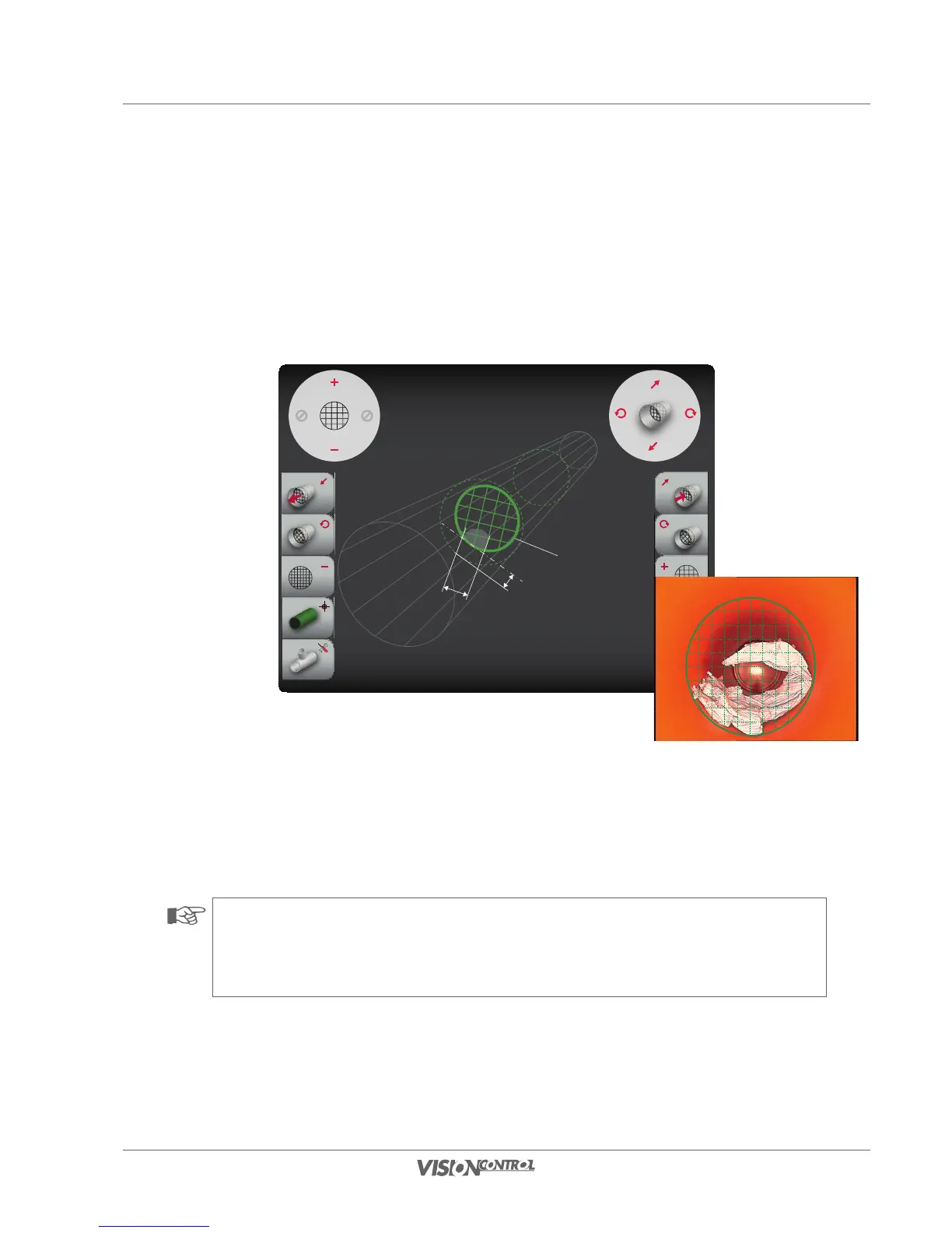
This function allows you to determine and measure objects located in the cross-section area of the pipe to be inspected. A virtual measuring grid
is projected optically on the cross-section level for this. You can then determine the dimensions of objects via the spacing of the measuring grid.
Examples of these measurements are tree root penetrations or coupling offsets.
CROSS-SECTION OBJECT:
Grid Unit: 5.00mm
Distance: 7.00mm
Rotation: 15.00°
Measuring line 1
Object
Width
REAL PIPE:
Diameter: 150.00mm
Length: 105.50mm
Rotation: 2.80°
Distance
• Use the right joystick (vertical deflection) or the L1/R1 buttons to determine the position of measuring line 1 in the direction of the
pipe axis.
• Use the right joystick (horizontal deflection) or the L2/R2 buttons to determine the rotation of measuring line 1.
• Scale the grid unit using the left joystick or the L3/R3 buttons.
NOTE!
You can determine the exact dimensions of the deformation or the damage point via the projected grid unit. You can read or convert
the values using the scale shown in the display.
REAL PIPE:
Diameter: 150.00mm
Length: 105.50mm
Rotation: 2.80°
CROSS SECTION OBJECT:
Grid Unit: 5.00mm
Distance: 7.00mm
Rotation: 15.00°
Sample calculation:
Object width = 2 grid units
i.e. 2 units x 5mm
Result:
Object width = 10mm