www.javad.com Maxor Operator’s Manual 3-19
SETUP AND MEASURING
Measuring with the Maxor
epoch to which the newly received RTCM/CMR message
corresponds) or the current stand-alone position (while waiting for
new RTCM/CMR messages coming from the base).
• Select the antenna status during RTK, either Static or Kinematic.
•
Specify the Ambiguity fixing level (not applic
able to RTK Float).
The Ambiguity Fixing Level radio buttons govern the process of
the RTK engine, fixing integer ambiguities. The RTK engine uses
the ambiguity fix indicator when making decisions whether or not
to fix ambiguities. Low, Medium, and High correspond to the
indicator's 95%, 99.5% and 99.9% states, respectively. The higher
the specified confidence level, the longer the integer ambiguity
search time.
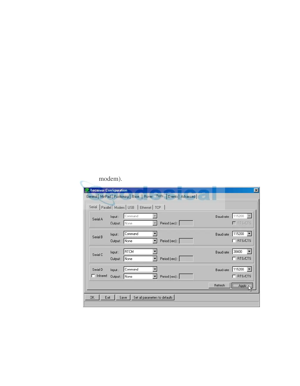
6. Select the Po
rts tab and
set the following parameters for Serial C
(Figure 3-14):
• Input drop-down list – select desired differential correction format.
• Period (sec) – leave as is.
• Baud rate drop-down list – select a baud rate (i.e
., the receiver port
baud rate at which differential messages will be received from
modem).
Figure 3-14. Rover Configuration – Ports
7. Click Apply.
8. Click OK to close the Receiver Conf
iguration screen.