JOHNSON CONTROLS
10
FORM 100.50-NOM12
ISSUE DATE: 04/02/2019
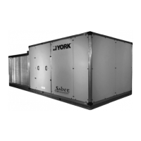
FIGURE 1 - Packaged Rooftop Air Conditioning Unit .............................................................................................13
FIGURE 2 - Double Sloped SS Drain Pan ..............................................................................................................15
FIGURE 3 - Unit Clearances ...................................................................................................................................18
FIGURE 4 - Lifting Lug Locations ............................................................................................................................19
FIGURE 5 - Drain Trap Showing Water Location During Draw Through Operation Stages ....................................28
FIGURE 6 - Trap Detail For Draw Through Application ...........................................................................................28
FIGURE 7 - Field Control Wiring - Inputs ................................................................................................................31
FIGURE 8 - Field Control Wiring - Outputs .............................................................................................................32
FIGURE 9 - Single-Point Power Supply Wiring ....................................................................................................... 34
FIGURE 10 - Single-Point Power Supply Wiring With Non-Fused Disconnect .......................................................35
FIGURE 11 - Dual-Point Power Supply Wiring ........................................................................................................36
FIGURE 12 - Static Pressure Probe Location .........................................................................................................38
FIGURE 13 - Typical Gas Piping Connection .......................................................................................................... 39
FIGURE 14 - Combustion Vent ...............................................................................................................................40
FIGURE 15 - Fan Isolator Spring Bolts (Total Of 8).................................................................................................42
FIGURE 16 - Manifold Gas Pressure Adjustment ...................................................................................................49
FIGURE 17 - Sheave Alignment ..............................................................................................................................52
FIGURE 18 - Fan Data Plate - Belt Tension ............................................................................................................53
FIGURE 19 - Belt Tensioning Gauge .......................................................................................................................53
FIGURE 20 - Forward Curved Fan Shaft/Wheel Marking .......................................................................................54
FIGURE 21 - Bearing With Setscrew Type Locking Device ....................................................................................55
FIGURE 22 - Bearing With Eccentric Cam ..............................................................................................................56
FIGURE 23 - Eccentric Cam Locking Collar Bearing Installation ............................................................................56
FIGURE 24 - Split Bearing ......................................................................................................................................57
FIGURE 25 - Unit Options ....................................................................................................................................... 59
FIGURE 26 - Single Zone VAV (SZVAV) and Constant Volume (CV) — Occupied and Unoccupied ......................66
FIGURE 27 - Active Duct Static Pressure Setpoint Vs. Duct Static Pressure Reset Voltage .................................. 68
FIGURE 28 - Active SAT Setpoint Versus SAT Reset Voltage ................................................................................70
FIGURE 29 - Active SAT Setpoint Versus RAT .......................................................................................................71
FIGURE 30 - Active SAT Setpoint Versus OAT .......................................................................................................71
FIGURE 31 - Active SAT Setpoint Versus Supply Fan Speed .................................................................................72
FIGURE 32 - Variable Air Volume (VAV) — Occupied .............................................................................................72
FIGURE 33 - VAV — Unoccupied ...........................................................................................................................73
FIGURE 34 - Compressor Safety Chain — Without Compressor Protection Module .............................................76
FIGURE 35 - Compressor Safety Chain — With Compressor Protection Module ..................................................77
FIGURE 36 - Compressor System Status Input To I/O Board .................................................................................77
FIGURE 37 - Low Pressure CutOut (LPCO) Switch Wiring ....................................................................................77
FIGURE 38 - HGRH 3-Way Stepper Valve..............................................................................................................80
FIGURE 39 - HGRH Control Board ......................................................................................................................... 81
FIGURE 40 - HGRH Piping Layout .........................................................................................................................82
FIGURE 41 - Evaporator Air Temperature Active Setpoint VS Return Air Humidity ................................................83
FIGURE 42 - HGRH SAT Active Setpoint vs Return Air Temperature ..................................................................... 83
FIGURE 43 - Condenser Fan Contactors — Fans 1A And 1B Only For Compressor System #1 ........................... 84
FIGURE 44 - Condenser Fan VFD Wiring — Condenser Fan 1A Shown ............................................................... 85
FIGURE 45 - Digital Multiplexor Connections For Staged Gas Heat ......................................................................87
FIGURE 46 - Modulating Gas Furnace Sections.....................................................................................................89
FIGURE 47 - Digital Multiplexor Connections For Modulating Gas Heat ................................................................90
LIST OF FIGURES
 Loading...


