JOHNSON CONTROLS
21
SECTION 2 – INSTALLATION
FORM 100.50-NOM12
ISSUE DATE: 04/02/2019
2
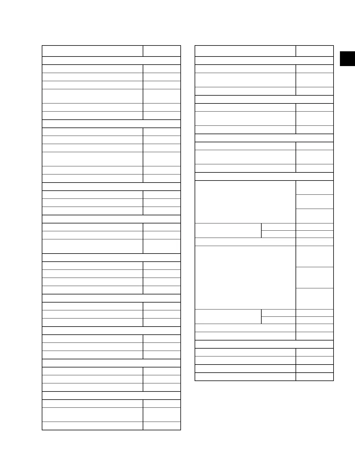
TABLE 3 - PHYSICAL DATA (CONT'D)
70 TON MODELS
MODEL SIZE 070
Optional Exhaust Fan
Quantity Fans/Motors 2 / 1
Type FC
Size 20-18
Motor Size Range (min. to max. HP, total
for two fans))
5–30
Airow Range (min. to max. CFM) 4000–36000
Static pressure range (min. to max. IWG) 0–2”
Optional Return Fan
Quantity Fans/Motors 2 / 2
Type Plenum
Size 270
Motor Size Range (min. to max. HP, total
for two fans))
10–30
Airow Range (min. to max. CFM) 4000–32000
Static pressure range (min. to max. IWG) 0-3”
Evaporator Coil
Size (square feet) 56.9
Number of rows / ns per inch 4/17
Tube Diameter / Enhanced Surface 3/8"/Enhanced
Condenser Coil
Size (square feet) 164
Number of rows / ns per inch 1/21
Tube Diameter / Surface
1 mm/
microchannel
Condenser Fans
Quantity 6
Type Prop.
Diameter (inches) 36
Power (HP each) 2
Filters - 2” Throwaway (Pre-Filter Position)
Quantity 10 / 15
Size (length x width) (in.) 25x16 / 25x20
Total Filter Face Area (square feet) 77.1
Filters - 2” Cleanable (Pre-Filter Position)
Quantity 10 / 15
Size (length x width) (in.) 25x16 / 25x20
Total Filter Face Area (square feet) 77.1
Filters - 2” Pleated, 30% Efficient (Pre-Filter Position)
Quantity 10 / 15
Size (length x width) (in.) 25x16 / 25x20
Total Filter Face Area (square feet) 77.1
Filters -12” Rigid 65%, 2” 30% Prefilter (Pre-Filter Position)
Quantity 2 / 8 / 9
Size (length x width) (in.)
16x20 /
25x16 / 25x20
Total Filter Face Area (square feet) 55.8
MODEL SIZE 070
Filters -12” Rigid 95%, 2” 30% Prefilter (Pre-Filter Position)
Quantity 2 / 8 / 9
Size (length x width) (in.)
16x20 /
25x16 / 25x20
Total Filter Face Area (square feet) 55.8
Filters - 2” Carbon (Pre-Filter Position)
Quantity 10 / 15
Size (length x width) (in.)
16x20 /
25x16 / 25x20
Total Filter Face Area (square feet) 77.1
Filters - 12” rigid 95% in Post-filter Position
Quantity 2 / 7 / 9
Size (length x width) (in.)
16x20 /
25x16 / 25x20
Total Filter Face Area (square feet) 55.1
Gas Furnace
Staged Furnace Sizes
(input/output/stages)
375 mbh / 300
mbh / 2 stages
750 mbh / 600
mbh / 4 stages
1125 mbh / 900
mbh / 6 stages
Inlet Gas Pressure Range
(min. to max. IWG)
Natural 4.5–10.5” w.c.
Propane 11.0–13.0” w.c.
Airow Range (min. to max. CFM) 6,950–36,000
Modulating Furnace Sizes
(input/output/turndown)
375 mbh /
300 mbh / 8:1
turndown
750 mbh / 600
mbh / 16:1
turndown
1125 mbh /
900 mbh /
24:1 turndown
Inlet Gas Pressure Range
(min. to max. IWG)
Natural 4.5–10.5” w.c.
Propane 11.0–13.0” w.c.
Minimum Heat Exchanger Entering SAT 40.0 °F
Airow Range (min. to max. CFM) 8,250–36,000
Electric Heaters
Size Range (min. to max. kW) 80–200
Heating Steps
1
2–6
Minimum OAT For Mech. Clg. 45
Low Ambient Option Min. OAT 0
1. Electric heat steps and airow range depends on voltage and
size. Consult the air pressure drop tables for specic number
of steps for a given voltage.
2. Weights are for components only and need to be added to the
extended cabinet weights. The diffuser is required in the ex-
tended cabinet for any unit with hot water or nal lter option.

 Loading...


