8─68
8.5 Adjustments
yyyy
yyyy
8
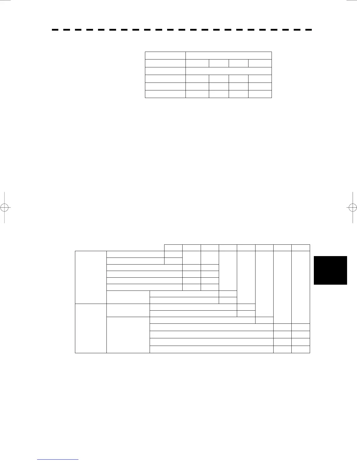
S5-7, -8 ...............................Log ratio
Pulse/NM (pulse signal)
800 400 200 100
Gyration/NM (synchro signal)
360X 180X 90X 36X
S5-7 OFF OFF ON ON
S5-8 OFF ON OFF ON
• S6:Log test. Set it to [NORMAL].
• S7: Normal or BSH(IMO) specifications selection. Set it to [NORMAL].
• Set JP1 according to the particular gyro.
[SYNC] .......................................Synchro signal
[STEP]......................................... Step signal
(2) Connect the gyro signal and the log signal cables to the NSK Circuit. (PC4201)
(3) Set S1 to [ON].
* After power-on operation, the switch S5-4 shall be set to [ON] if the radar video and the indicated value of
COURSE (own ship’s true bearing) is reversed.
Table 8-19 Gyro and Log Select Switches (S5 Dip Switch)
S5 Setting Table
1 2 3 4 5 6 7 8
SYNC 0
STEP 1
360X 0 0
180X 0 1
90X 1 0
36X 1 1
Normal (NOR) 0
GYRO SIG.
DIRECTION
Reverse (REV) 1
PULSE 0
TYPE
SYNCHRO 1
0
800P/360X
0 0
400P/180X
0 1
200P/90X
1 0
LOG SIG.
PULSE/NM
100P/30X
1 1
 Loading...


