5─16
5.2 ATA OPERATION
yy
yyy
5
5.2.4 ATA Data Display
(Refer to Example of Display in page 2-1. )
Display of Vectors
A vector to represent a target’s predicted position can presented in the True vector or Relative vector mode. In
each mode, a vector length can be freely changed for a time interval of 1 to 60 minutes.
The True and Relative vector can be switched by using buttons
47
shown in the radar display on page 2-7.
[I] Vector Mode Selection
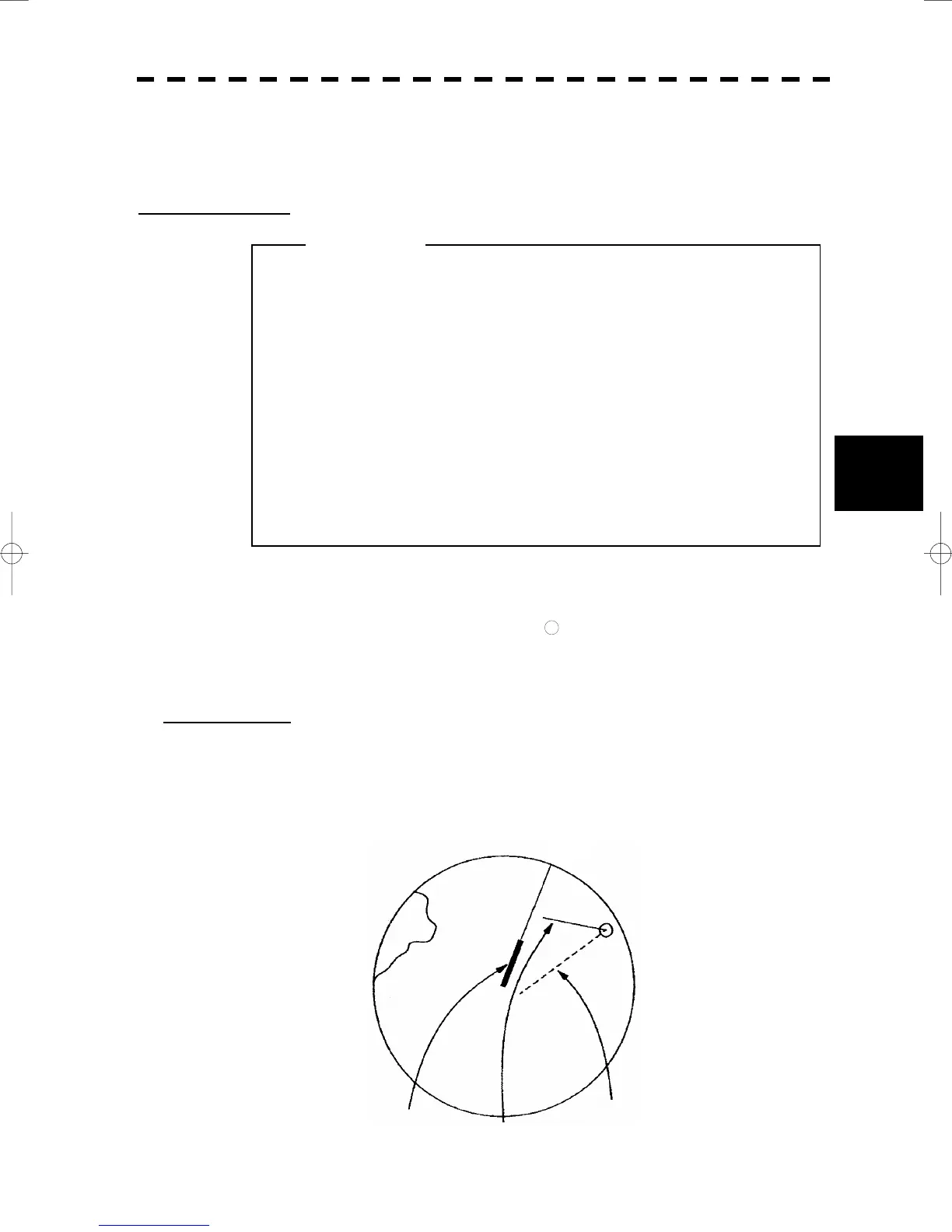
True Vector Mode
In the true vector mode, the direction of a target vector indicates the true course of the target and its vector
length is proportional to its speed.
In this mode, own ship’s vector is displayed as shown below.
In this mode, the movements of other ships around own ship can be accurately and easily monitored.
However, no CPA RING can appear in this mode.
When a target or own ship changes a course, or when a
target is acquired, its vector may not reach a given
level of accuracy until three minutes or more has
passed after such course change or target
acquisition.
Even if three minutes or more has passed, the vector
may include an error depending upon the tracking
conditions.
n
i
n
Own Ship’s Vector
True Vector
The relative vector is not displayed
HL

 Loading...


