1. Wrap and fasten one end of the ESD grounding strap around your bare wrist and connect the other
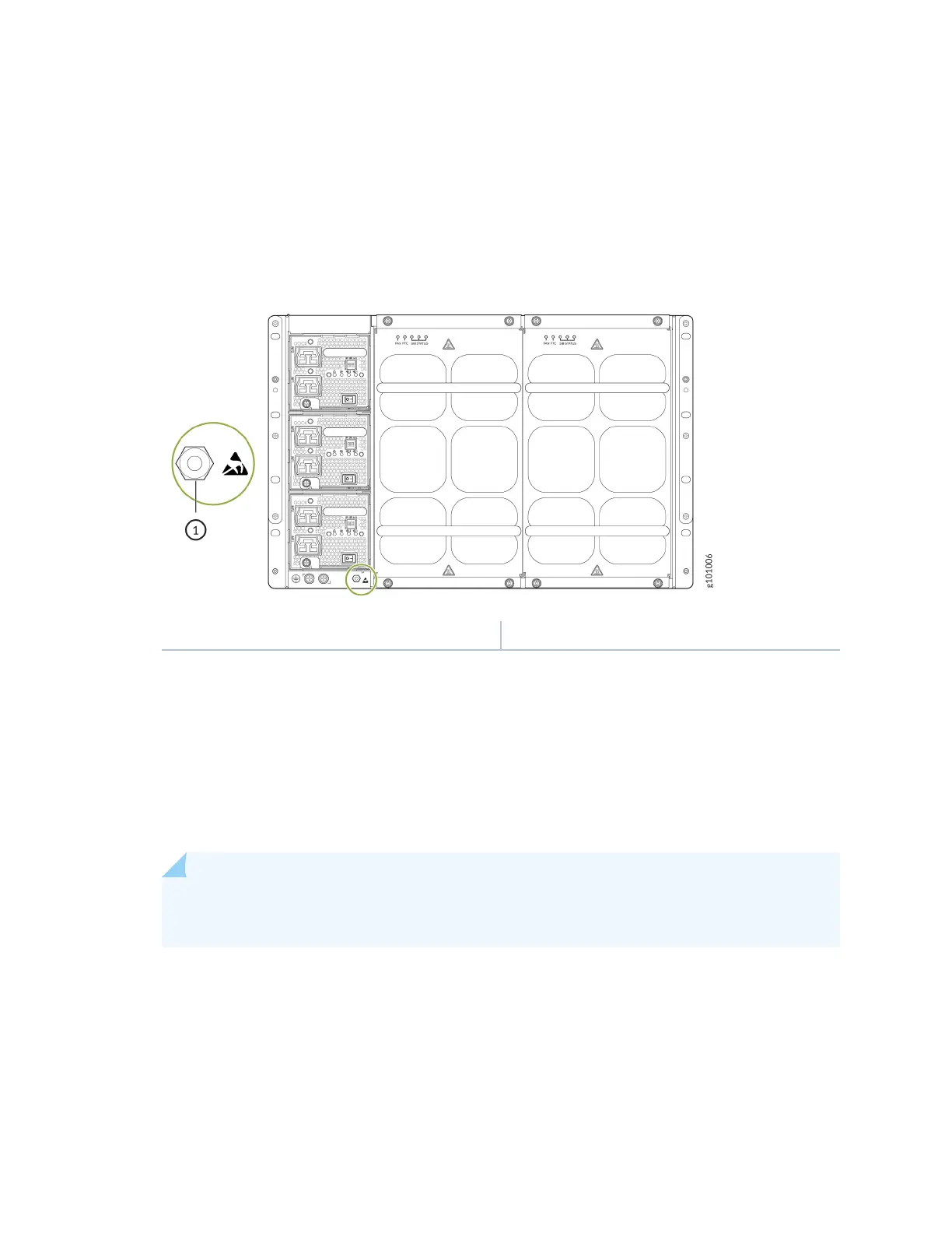
end of the strap to an ESD point on the chassis. An ESD point is located next to the protecve
earthing terminal and below PSU2 on the rear of the MX10004 (see Figure 57 on page 149).
Figure 57: ESD Point on the Rear of the MX10004
1— ESD point
2. Taking care not to touch power supply connecons, remove the power supply from its bag.
3. Peel back and remove the protecve plasc wrap that covers all four sides of the power supply.
4. Ensure that the power switch is set to the standby (O) posion. This switch turns o the output
voltage; it doesn’t interrupt input power.
5. Unscrew the capve screw in the counterclockwise direcon by using the Phillips (+) screwdriver,
number 1.
6. Rotate the capve screw away from the faceplate of the power supply to release the latch.
NOTE: You can install the power supplies in any slot labeled PSU 0 through PSU 2 (top to
boom) on an MX10004.
7. Using both hands, place the power supply in the power supply slot on the rear of the system. Slide
the power supply straight into the chassis unl the power supply is fully seated in the slot. Ensure
149