that the power supply faceplate is ush with any adjacent power supply faceplates or power supply
covers (see Figure 58 on page 150).
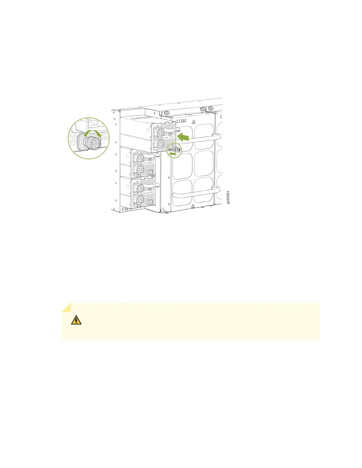
Figure 58: Install a JNP10K-PWR-AC2
8. Push the capve screw into the power supply faceplate. Ensure that the screw is seated inside the
corresponding hole on the faceplate.
9. Tighten the capve screw by turning it clockwise with the Phillips (+) screwdriver, number 1. When
the screw is completely ght, the latch locks into the router chassis.
10. Aach each power cable to a dedicated power source (A and B). The JNP10K-PWR-AC2 only
requires that each power supply be connected to a separate source.
11. For each power cable, insert the end of the cable with the Anderson connector into the JNP10K-
PWR-AC2 power supply. The connector snaps and locks the cable into posion.
WARNING: Ensure that the power cords do not block access to router components
or drape where people can trip on them.
12. If the AC or DC power source outlets have a power switch, set them to the on (|) posion.
13. Set the three DIP switches to set the inputs and whether the power supply is running at 3000 W,
5000 W, or 5500 W. See Table 50 on page 151.
Set both switch 1 and switch 2 to the on posion when using both power source inputs; power is
shared. When not using source redundancy, set the unused source to the o (O) posion. The LED
turns red and indicates an error if a source input is not in use and the DIP switch is on (|).
150