17. Tighten the captive screw by turning it clockwise by using the number 1 Phillips (+) screwdriver. When
the screw is completely tight, the latch locks into the router chassis.
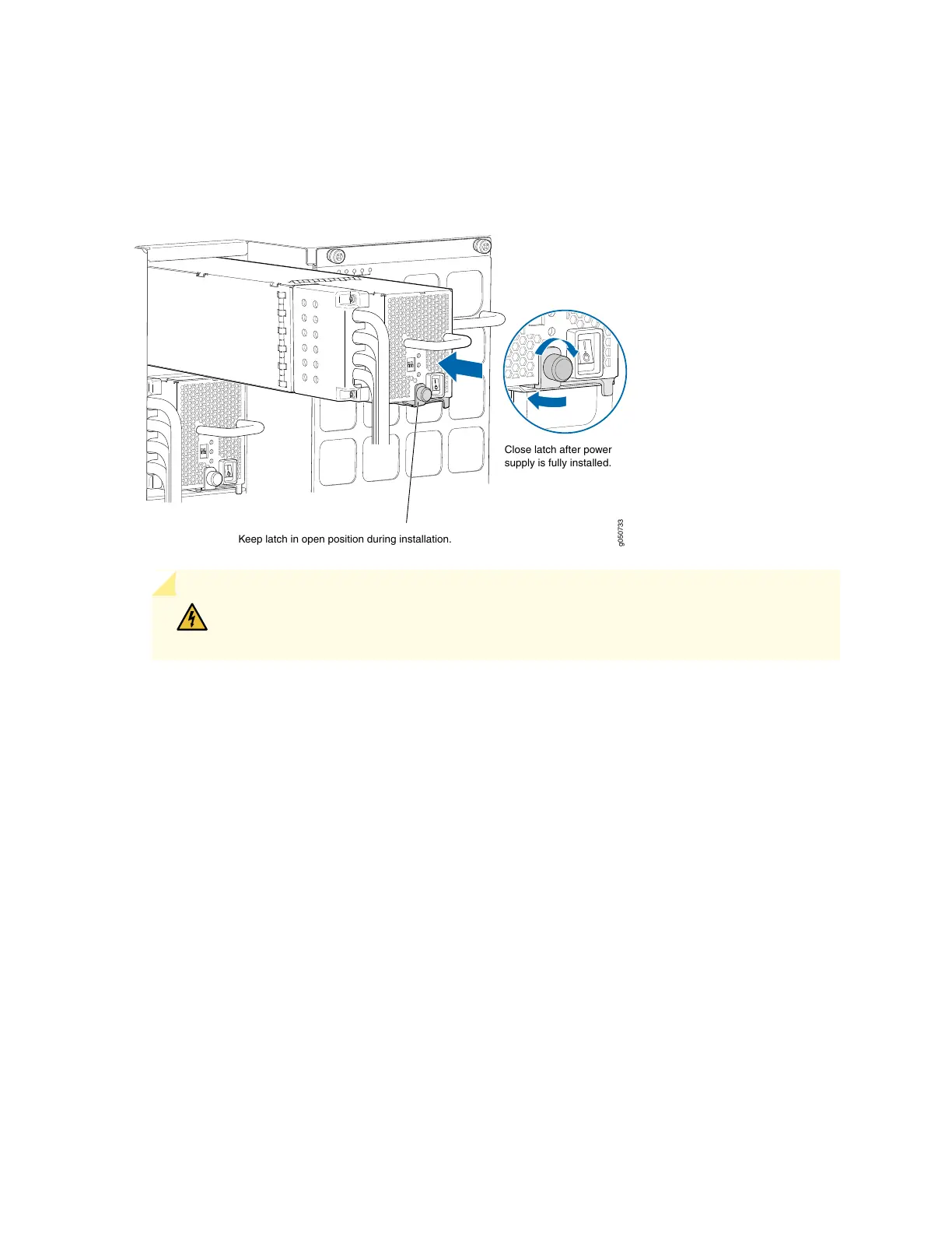
Figure 89: Installing a JNP10K-PWR-DC Power Supply in an MX10016
g050733
Keep latch in open position during installation.
Close latch after power
supply is fully installed.
WARNING: Ensure that the power cords do not block access to router components
or drape where people can trip on them.
18. Set the enable switches for input 1 and input 2 (see Figure 90 on page 197).
Set both enable switches to the | (on) position when using both source inputs. When not using source
redundancy, set the enable switch of the unused source to the O (off) position. The FAULT LED on the
power supply turns red to indicate an error if a source input is not in use and the corresponding enable
switch is set to the on (|) position.
196