power feeds derived from feed INPUT 1 and feed INPUT 2. This configuration provides the commonly
deployed INPUT 1 / INPUT 2 feed redundancy for the router. There is basic insulation between the
inputs and the chassis ground, and also, there is basic insulation between the RTN input feeds.
10. Install the plastic cable cover over each set of power cables by using the number 2 Phillips (+) screwdriver,
to tighten the screw.
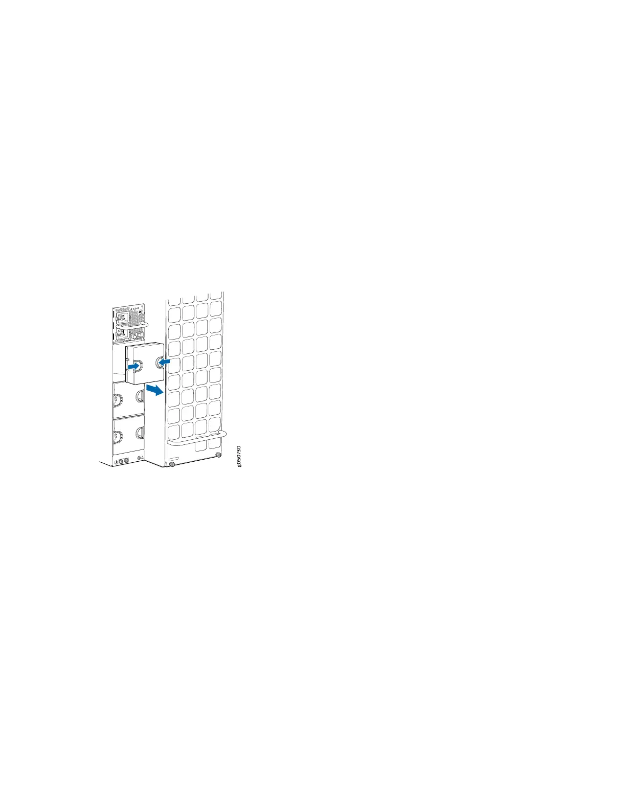
11. If the power supply slot on the chassis has a cover panel on it, insert your thumb and forefinger into
the finger holes, squeeze, and then pull the cover panel out of the slot. Save the cover panel for later
use (see Figure 88 on page 195).
Figure 88: Removing the Cover Panel of a Power Supply on an MX10016
12. Unscrew the captive screw by turning it counterclockwise by using the number 1 Phillips (+) screwdriver.
13. Pull the captive screw on the latch away from the faceplate of the power supply to release the latch.
14. Using both hands, place the power supply in the power supply slot on the rear of the router.
15. Slide the power supply straight into the chassis until the power supply is fully seated in the slot. Ensure
that the power supply faceplate is flush with any adjacent power supply faceplates or power supply
cover panels (see Figure 89 on page 196).
16. Push the captive screw of the latch into the power supply faceplate. Ensure that the screw is seated
inside the corresponding hole on the faceplate.
195