3. Ensure the black power supply output router, to the right of the captive screw, is set to the standby
position.
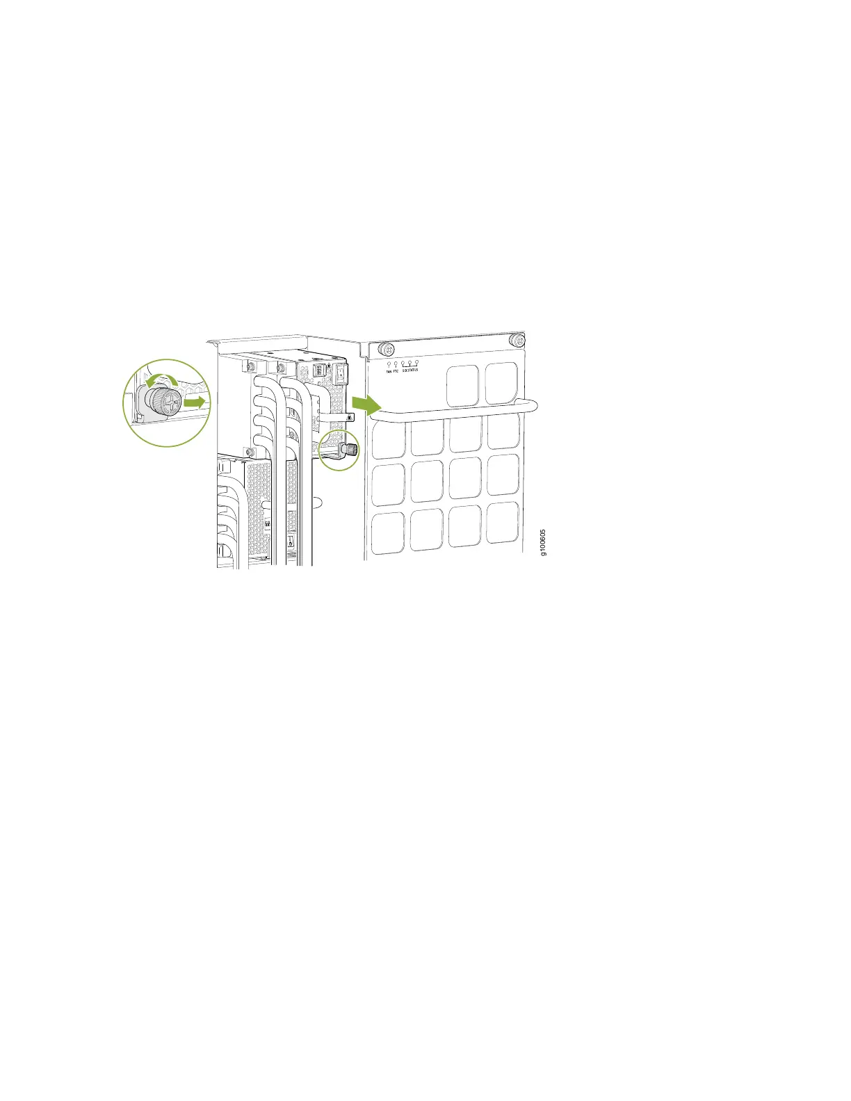
4. Unscrew the captive screw counterclockwise by using the Phillips (+) screwdriver, number 1.
5. Rotate the captive screw away from the faceplate of the power supply to release the latch. (See
Figure 92 on page 199.)
Figure 92: Removing a JNP10K-PWR-DC2 Power Supply on an MX10016
6. Put on the heat resistant gloves to protect your hands from the hot power supply.
7. Taking care not to touch power supply components, pins, leads, or solder connections, place one gloved
hand under the power supply to support it. Grasp the power supply handle with your other hand and
pull the power supply completely out of the chassis.
8. If you are not replacing the power supply, install the cover panel over the slot.
a. Insert your thumb and forefinger into the finger holes of the cover panel.
b. Squeeze and place the cover in the slot.
c. Release your fingers and the cover remains in the slot.
9. Unscrew the screw on the plastic cable cover that shield the input terminal studs counterclockwise by
using the Phillips (+) screwdriver, number 2.
199