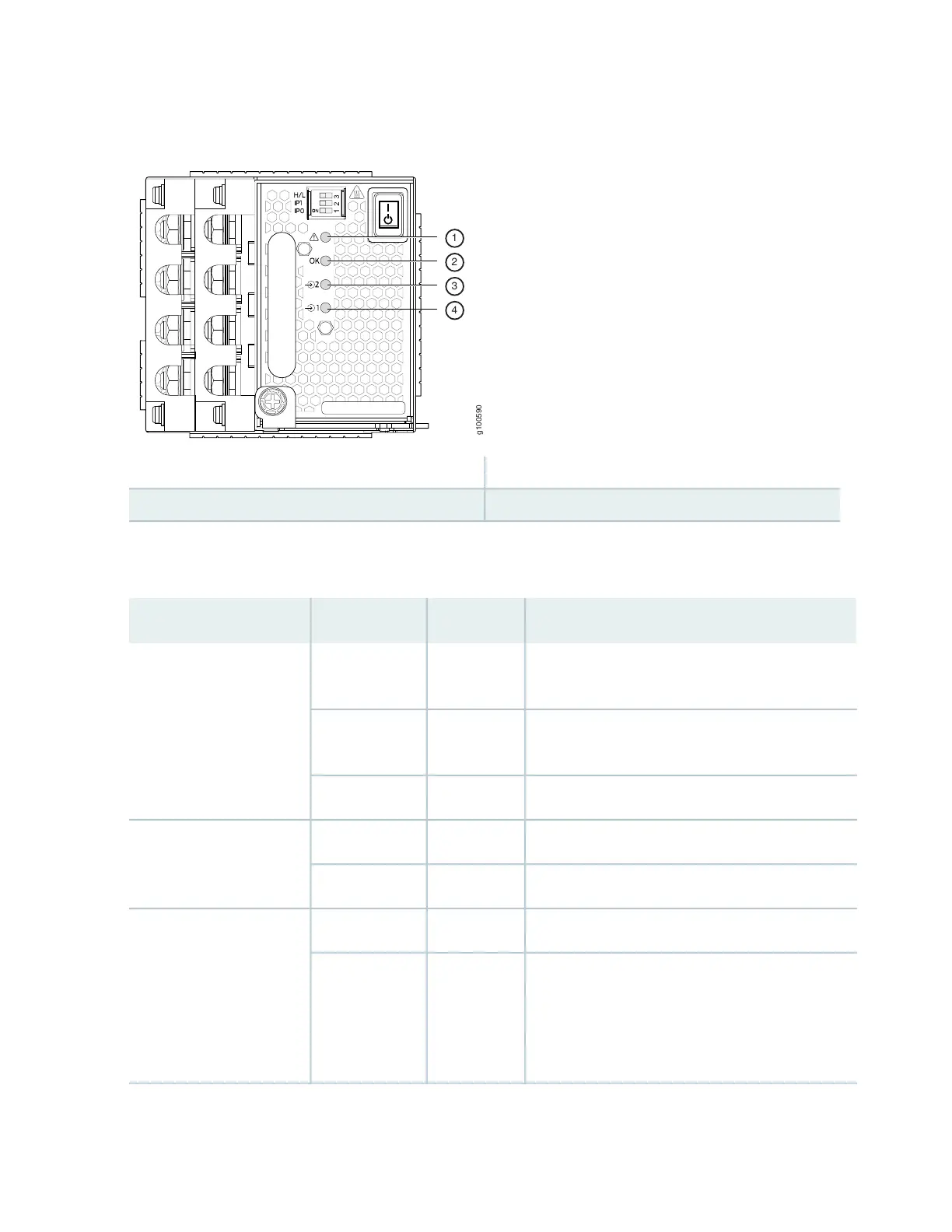
Figure 32: LEDs on a JNP10K-PWR-DC2 Power Supply
3—1— 2–Source input 1!–FAULT
4—2— 1–Source input 0OK–Power okay
Table 20 on page 74 describes the LEDs on a JNP10K-PWR-DC2 power supply.
Table 20: LEDs on a JNP10K-PWR-DC2 Power Supply
DescriptionStateColorLED
Indicates the DC power input voltage is not within
normal operating range.
BlinkingYellow1 (INP0 in CLI output) or 2
(INP1 in CLI output)
DC power is within operating range (-40 VDC to -72
VDC).
SolidGreen
The power supply is switched off.OffUnlit
DC power output is within normal operating range.SolidGreenOK
The output is out of the limits.BlinkingYellow
Power supply has failed and must be replaced.SolidRed!
Power supply is functioning normally. Or, only one
input is powered and the enable switch for the input
that is not powered is set to ON. See “Connecting
DC Power to an MX10016” on page 149 for more
information on the enable switches.
OffUnlit
74