Model 6517B Electrometer Reference Manual Section 5: Measurement options
6517B-901-01 Rev. C / August 2015 5-13
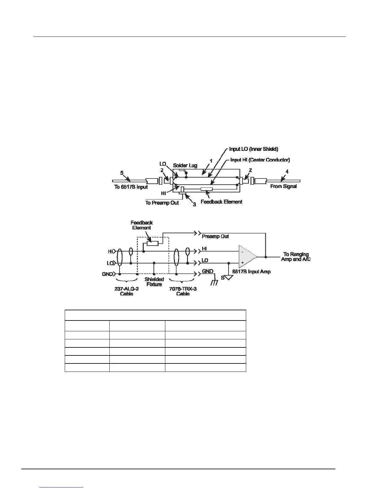
Shielded fixture construction
Since shielding is so critical for proper operation of external feedback, it is recommended that a
shielded fixture similar to the one shown in the figure below be used to house the feedback element.
The fixture is constructed of a commercially available shielded fixture modified with the standard BNC
connectors replaced with triaxial female connectors. For convenience, a banana jack can be mounted
on the box to make the necessary PREAMP OUT connection.
Alternately, a wire could be run through a rubber grommet mounted in a hole in the side of the box.
Note that input low is connected to chassis ground within the shielded box. This connection can be
made by using a small solder lug secured with a screw.
Figure 62: Shielded fixture construction
Figure 63: Shielded fixture construction - equivalent circuit
Parts list
Item Description MFR part number
1 Shielded fixture Pomona #2390
2 Female triaxial Keithley 7078-TRX-TBC
3 Banana jack Keithley BI-9-2
4 Triaxial cable Keithley 237-ALG-2
5 Triaxial cable Keithley 7078-TRX-3

 Loading...


