Section 4: Basic measurements Model 6517B Electrometer Reference Manual
4-10 6517B-901-01 Rev. C / August 2015
Basic measurement procedure
To achieve optimum precision for low-level current measurements, input bias current and voltage
burden can be minimized by performing the offset adjustment procedure.
After measuring high voltage in the volts function, it may take a number of minutes for input current
to drop to within specified limits. Input current can be verified by placing the protection cap on the
INPUT triaxial connector and then connecting a jumper between COMMON and chassis ground.
With the instrument on the 20 pA range and zero check disabled, allow the reading to settle until the
input bias current is within specifications.
Perform the following steps to measure current. To ensure proper operation, always enable zero
check (“ZeroCheck” displayed) before changing functions (V, I, R, or Q). The Z-CHK key controls
zero check.
1. With zero check enabled (“ZeroCheck” displayed), select the amps (I) function. The Z-CHK key
toggles zero check between the on and off states. Note that the input circuit configuration
changes with zero check enabled.
2. To achieve optimum accuracy for low current measurements, it is recommended that you zero
correct the instrument. To do so, select the lowest measurement range (20 pA) and press REL.
The REL indicator turns on and the “ZCor” message is displayed. Correcting zero on the lowest
range corrects all ranges because of internal scaling.
3. Select a manual measurement range that is consistent with the expected reading, or enable auto
range.
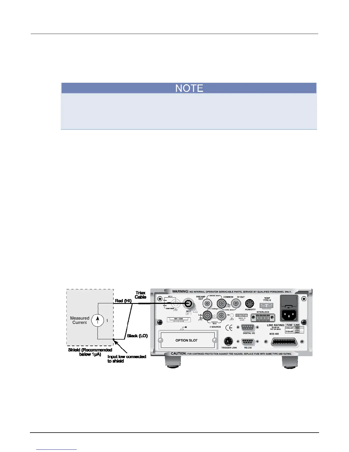
4. Connect the Model 6517B to the current to be measured. The figure below shows typical
connections for current measurements. If measuring current in a floating circuit where significant
leakage may exist between the ammeter input and circuit low, connect the Model 6517B to the
circuit as shown in the next figure, "Connections for guarded, floating current measurements."
Notice that ammeter input LO is connected to circuit high. Also note that a safety shield should be
used if the input of the ammeter is floating at a hazardous voltage level (V
F
≥ 30 V).
5. Press Z-CHK to disable zero check and take a reading from the display. To disable zero correct,
enable zero check and press REL.
Figure 34: Current measurements - typical connections
Figure 35: Current measurements - equivalent circuit

 Loading...


