EasyManuals Logo

Keithley 6517B Reference Manual

Keithley 6517B
498 pages
To Next Page IconTo Next Page
To Previous Page IconTo Previous Page
Page #165 background imageLoading...
Page #165 background image
Section 7: Triggering Model 6517B Electrometer Reference Manual
7-22 6517B-901-01 Rev. C / August 2015
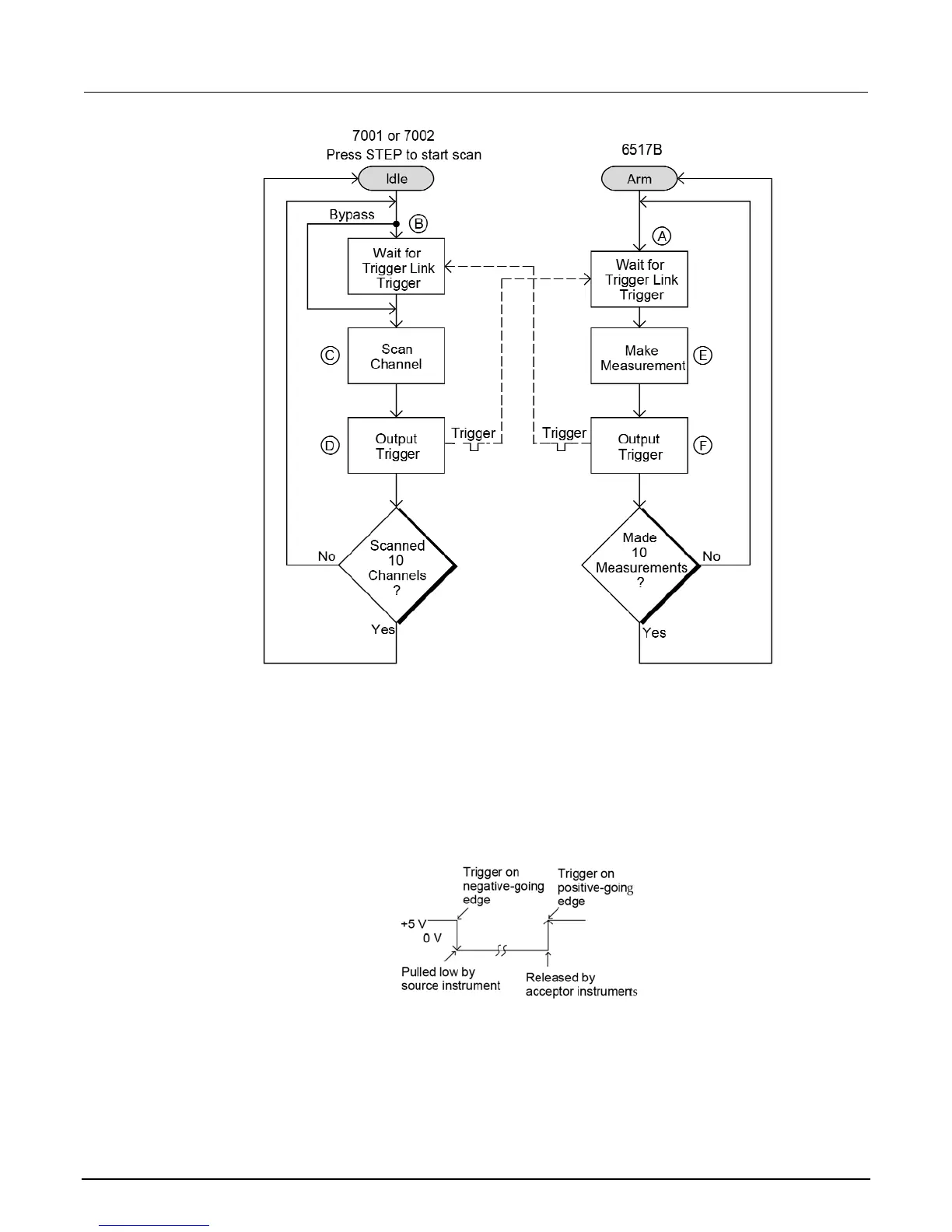
Semi-synchronous operation
In the Semi-synchronous trigger link mode, all triggering (input and output) is controlled by a single
line. When the normally high (+5 V) trigger line is pulled low (0 V), a trigger occurs on the negative-
going edge. When the trigger line is released, a trigger occurs on the positive-going edge. See the
following figure for an example. The advantage of this single line trigger is that as long as one of the
instruments in the system holds the line low, the trigger is suppressed. In other words, the trigger
does not occur until all instruments in the system are ready.
Figure 85: Semi-synchronous trigger link specifications

Table of Contents

Other manuals for Keithley 6517B

Questions and Answers:

Question and Answer IconNeed help?

Do you have a question about the Keithley 6517B and is the answer not in the manual?

Keithley 6517B Specifications

General IconGeneral
Input Impedance>200 TΩ
Electrometer TypeElectrometer/High Resistance Meter
Current Measurement Range20 fA to 20 mA
DisplayVacuum Fluorescent Display
Communication InterfacesIEEE-488 (GPIB), RS-232
Power Supply100 V / 120 V / 220 V / 240 V; 50 Hz / 60 Hz
Resistance Measurement RangeUp to 200 TΩ

Related product manuals