Section 2: Getting started Model 6517B Electrometer Reference Manual
2-26 6517B-901-01 Rev. C / August 2015
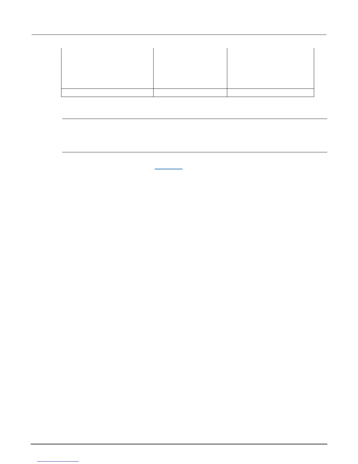
V-source:
Range
Voltage Limit
Value
Resistive I-Limit
Meter Connect
100 V
Off
1000 V
Off
Off
100 V
Off
1000 V
Off
Off
Zero Check On On
Note: The default selects all elements except HUM, DT, and ET.
COMMUNICATION
The COMMUNICATION menu option allows you to select and configure the GPIB or RS-232 bus.
See Section 11 for details.
CAL
The CALIBRATION menu is used for viewing the calibration dates and setting the option to display
calibration dates on power up. See Section 15 (on page 15-1) for calibration information.
TEST
The SELF-TEST menu is used as a diagnostic tool to isolate problems with the Model 6517B front
panel display. Each SELF-TEST menu item features prompts to guide the user through the
diagnostics.
LIMITS
The LIMITS menu is used to set and control the limit values that determine the PASS/FAIL and HI/LO
status of subsequent measurements and to set the digital output patterns that signify passing or
failing limit checks. See Section 10 for details.
STATUS-MSG
This selection is used to enable or disable the status messages mode. When enabled, status
messages are displayed to identify specific operations that are performed.
ON: Enable the status message mode
OFF: Disable the status message mode
The instrument may become so busy displaying status messages, that key presses are no longer
acknowledged. You may have to clear status message display by pressing the EXIT key or sending a
bus command (:DISPlay:SMESsage OFF) to exit this mode.

 Loading...


