Model 6517B Electrometer Reference Manual Section 7: Triggering
6517B-901-01 Rev. C / August 2015 7-25
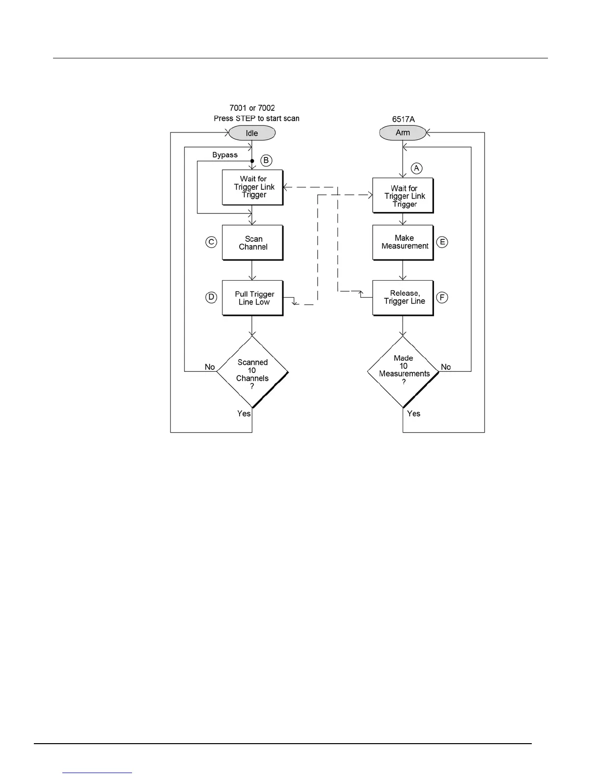
Figure 88: Operational model for semi-synchronous trigger link example
a. The BENCH RESET condition arms the Model 6517B and places electrometer operation at
point A in the flowchart, where it is waiting for a trigger link trigger. Note that since both the arm
layer and scan layer are programmed for immediate source, operation immediately drops down to
the measure layer at point A.
b. Pressing STEP takes the Model 7001/7002 out of the idle state and places operation at point B in the
flowchart. Since both the arm layer and scan layers are programmed for Immediate Spacing, operation
drops down to the Channel Layer at point B.
c. Since Channel Trigger source is set to source, the scan does not wait at point B for a trigger. Instead, it
bypasses "Wait for Trigger Link Trigger" and closes the first channel (point C). Note that the Bypass is
in effect only on the first pass through the model.
d. After the relay settles, the Model 7001/7002 pulls down the trigger link trigger line (point D). Since the
instrument is programmed to scan ten channels, operation loops back up to point B, where it waits for
an input trigger. Note that Bypass is no longer in effect.
e. Remember that the Model 6517B operation is at point A waiting for a trigger. When the trigger line is
pulled low by the Model 7001/7002, the leading negative-going edge triggers the Model 6517B to
measure DUT #1 . Note that the electrometer holds the trigger line low. After the measurement is
complete, The Model 6517B releases the trigger line.
f. The trigger line loops back to point A where it waits for another input trigger.
When the Model 6517B releases the trigger line, the leading positive-going edge triggers the Model
7001/7002 to close the next channel in the scan. This pulls the trigger line low, triggering the Model
6517B to measure the next DUT. The process continues until all ten channels are scanned and
measured.

 Loading...


