Model 6517B Electrometer Reference Manual Section 10: Limits, digital I/O, and scanning
6517B-901-01 Rev. C / August 2015 10-9
Outputs used as logic inputs
To use the digital outputs as logic inputs to active TTL, Low-power TTL, or CMOS inputs:
1. Connect the Model 6517B digital outputs to the logic inputs.
2. Connect the digital grounds.
3. Using the STATE menu, check output state setting of the Model 6517B output lines. The STATE
value for each output used should be ON.
4. Using the LOGIC-SENSE menu, check the logic-sense setting of the Model 6517B output lines
(TTL1 through TTL4). Make sure the correct LOGIC-SENSE value is selected for each output
line. The LOGIC-SENSE value varies according to the type of TTL, Low-power TTL, or CMOS
inputs used (ACTIVE-HIGH or ACTIVE-LOW).
When output is low (0 V), the output sink can drive at least 10 standard TTL inputs. When output is
high (+5 V), the 10 k pull-up resistor sources >100 µA while remaining at a > 3.75 V output (a
reliable logic high). If any LIMITS control is enabled (LOLIM1 or 2, HILIM1 or 2, High, Low, or Pass),
the OUTPUT-STATE menu does not check or change the output status.
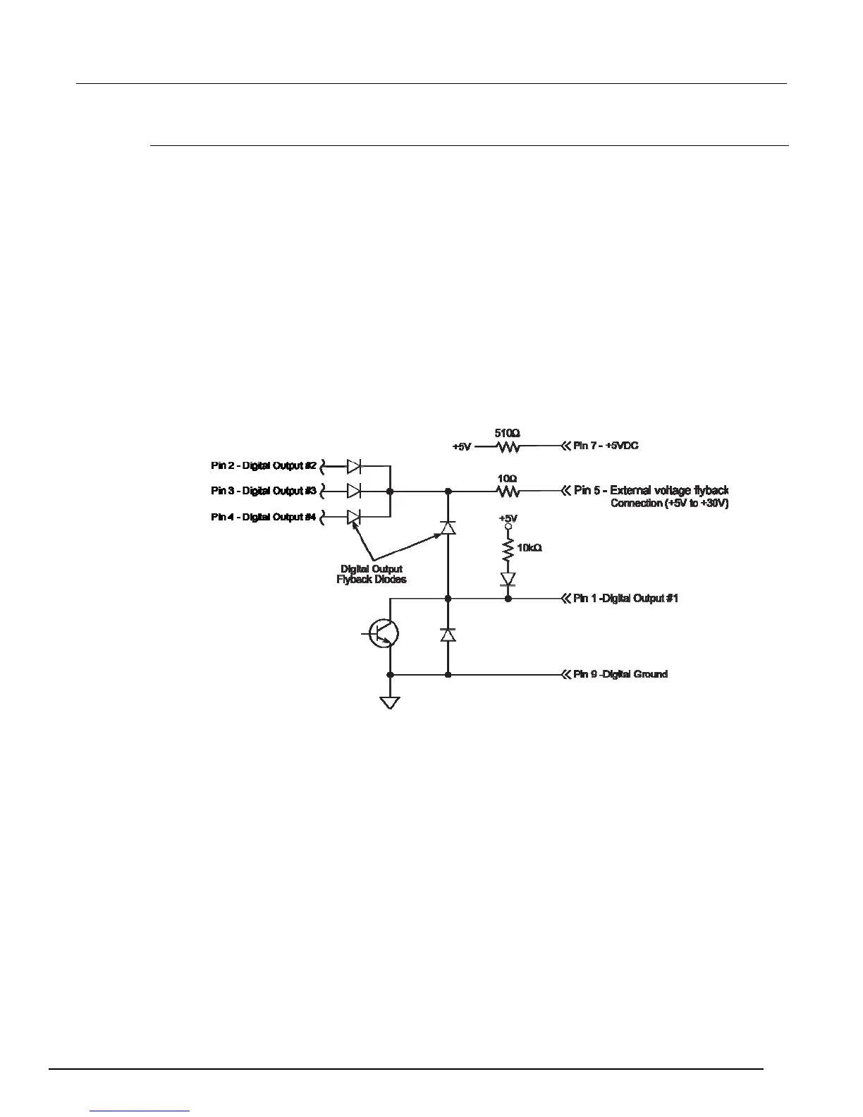
Figure 96: Digital I/O schematic
Figure 97: Digital I/O external relay control

 Loading...


