Section 16: Verification procedure Model 6517B Electrometer Reference Manual
16-6 6517B-901-01 Rev. C / August 2015
2. Turn on the Model 6517B and allow it to warm up for at least two hours before making
measurements.
3. Restore the Model 6517B to factory default settings using the procedure described in the topic
Considerations (on page 16-3).
4. Select the amps function and the 20 pA range on the Model 6517B. Refer to Amps configuration
(on page 4-12) for more information.
5. With zero check enabled, press REL to turn on the zero correct function.
6. Set the calibrator to 0.0 V, and then turn off zero check. Allow the reading to stabilize completely
before continuing.
7. Press REL to enable the Model 6517B REL function.
8. Using the formula:
V =I R
calculate the actual calibrator voltage to achieve the desired current using the known value of the
precision resistors. Record the calibrator voltage.
9. Set the calibrator to the actual voltage. See the calibrator documentation for detailed instructions.
10. Make sure the calibrator is in operate.
11. Allow the reading to settle completely, and note the reading on the Model 6517B. Verify that the
reading is within the limits specified in the table below.
12. Reverse the calibrator polarity, and verify the magnitude of the current reading is within the limits.
13. Turn zero-check on.
14. Repeat steps 4 through 13 for the 200 pA to 2 µA ranges using the appropriate DC voltage and
standard resistor listed in the table below.
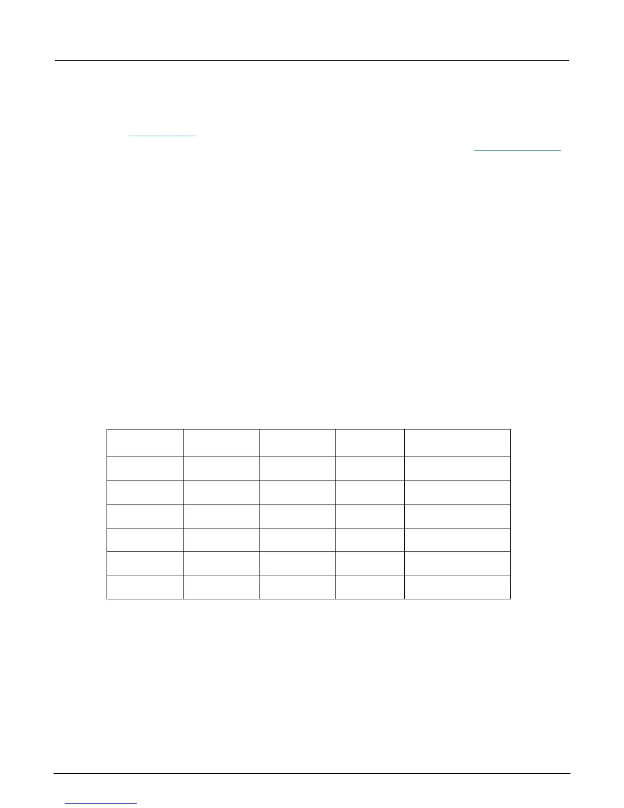
Reading limits for verification of 20 pA to 2 µA ranges
Model 6517B
range
Nominal DC
voltage value
Standard
resistor value
Applied
current
Reading limits
18° C to 28° C, 1 year
20 pA 1.9 V 100 GΩ 19 pA
18.8070 pA to
19.1930 pA
200 pA 1.9 V 10 GΩ 190 pA
188.095 pA to
191.905 pA
2 nA 1.9 V 1 GΩ 1.9 nA
1.89590 nA to
1.91410 nA
20 nA 1.9 V 100 MΩ 19 nA
18.9615 nA to
19.0385 nA
200 nA 19 V 100 MΩ 190 nA
189.615 nA to
190.385 nA
2 µA 190 V 100 MΩ 1.9 µA
1.89800 µA to
1.90200 µA

 Loading...


