Section 3: Connections Model 6517B Electrometer Reference Manual
3-8 6517B-901-01 Rev. C / August 2015
Use noise shield for:
Unguarded voltage measurements
Unguarded current measurements (below 1 µA)
Low-level charge measurements
Typically, the noise shield is connected to electrometer input LO. However, sometimes better noise
performance can be achieved by instead connecting the noise shield to both electrometer LO and
chassis ground. Electrometer LO can be connected to chassis ground at the rear panel of the Model
6517B by installing the ground link between the COMMON binding post and the chassis ground
binding post. You may have to experiment to determine which method provides the best noise
performance.
Do not make floating measurements with electrometer LO connected to chassis ground. If the rear
panel ground link is installed between COMMON and chassis ground, remove it before floating the
instrument.
Guard shield
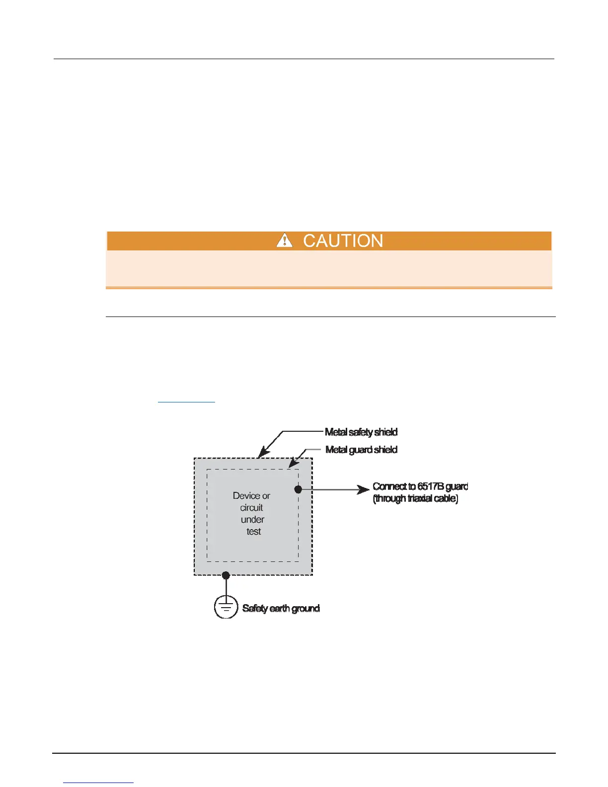
Guarding is used to greatly reduce leakage current in a high impedance test circuit. Leakage
resistance exists in the input cable (between conductor paths) and in the test fixture (at connectors
and insulators). The concept of guarding is to surround the input high node or DUT with a guard
shield that is at the same potential. Current cannot flow through a leakage resistance that has a 0 V
drop across it. A typical connection for the guard shield is shown in the following figure. Notice that a
safety shield is also used since guarded measurements can place hazardous voltages on the guard
shield (see Safety shield (on page 3-9)).
Figure 19: Guard shield

 Loading...


