EasyManuals Logo

Keithley 6517B Reference Manual

Keithley 6517B
498 pages
To Next Page IconTo Next Page
To Previous Page IconTo Previous Page
Page #67 background imageLoading...
Page #67 background image
Section 3: Connections Model 6517B Electrometer Reference Manual
3-14 6517B-901-01 Rev. C / August 2015
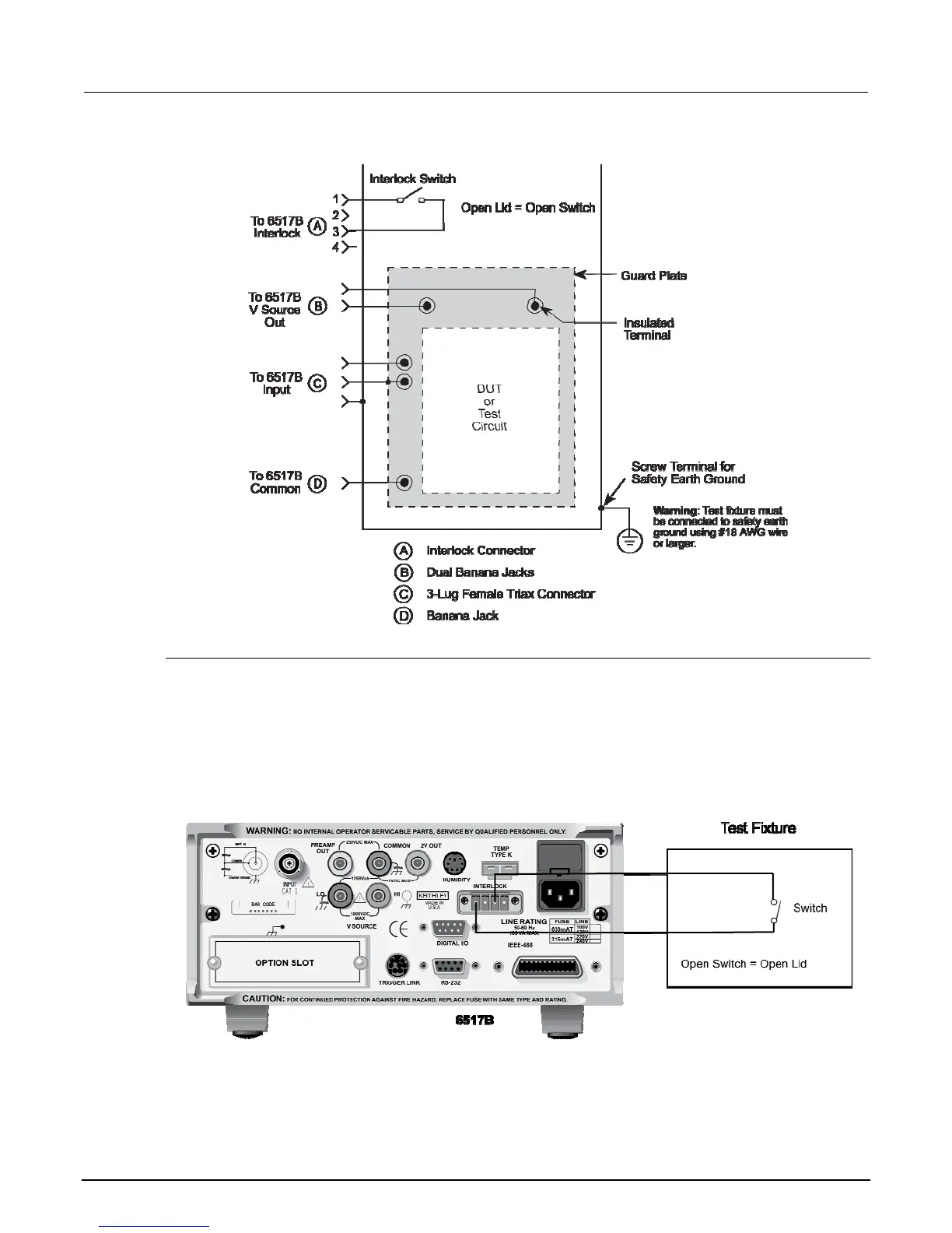
Figure 25: Multipurpose test fixture
Interlock
When a normally-open, SPST momentary switch is properly implemented as a safety interlock, the V-
source goes into standby whenever the test fixture lid is open or ajar.
The switch must be mounted inside the test box such that it is closed when the lid of the test fixture is
closed. Opening the lid must cause the interlock switch to open. There must never be enough
clearance to allow finger access inside the box while the switch is closed. The interlock must be
designed so that it cannot be defeated. See the following figure for typical interlock connections.
Figure 26: Interlock connections

Table of Contents

Other manuals for Keithley 6517B

Questions and Answers:

Question and Answer IconNeed help?

Do you have a question about the Keithley 6517B and is the answer not in the manual?

Keithley 6517B Specifications

General IconGeneral
Input Impedance>200 TΩ
Electrometer TypeElectrometer/High Resistance Meter
Current Measurement Range20 fA to 20 mA
DisplayVacuum Fluorescent Display
Communication InterfacesIEEE-488 (GPIB), RS-232
Power Supply100 V / 120 V / 220 V / 240 V; 50 Hz / 60 Hz
Resistance Measurement RangeUp to 200 TΩ

Related product manuals