346 Keysight N9927-90001 User’s Guide
5G Rapid Prototype Phased Array Antenna – Option 360
How to Set Up Phased Array Antenna Settings
— Clear Graphics If applicable, this clears the current displayed PNG
graphic from the screen.
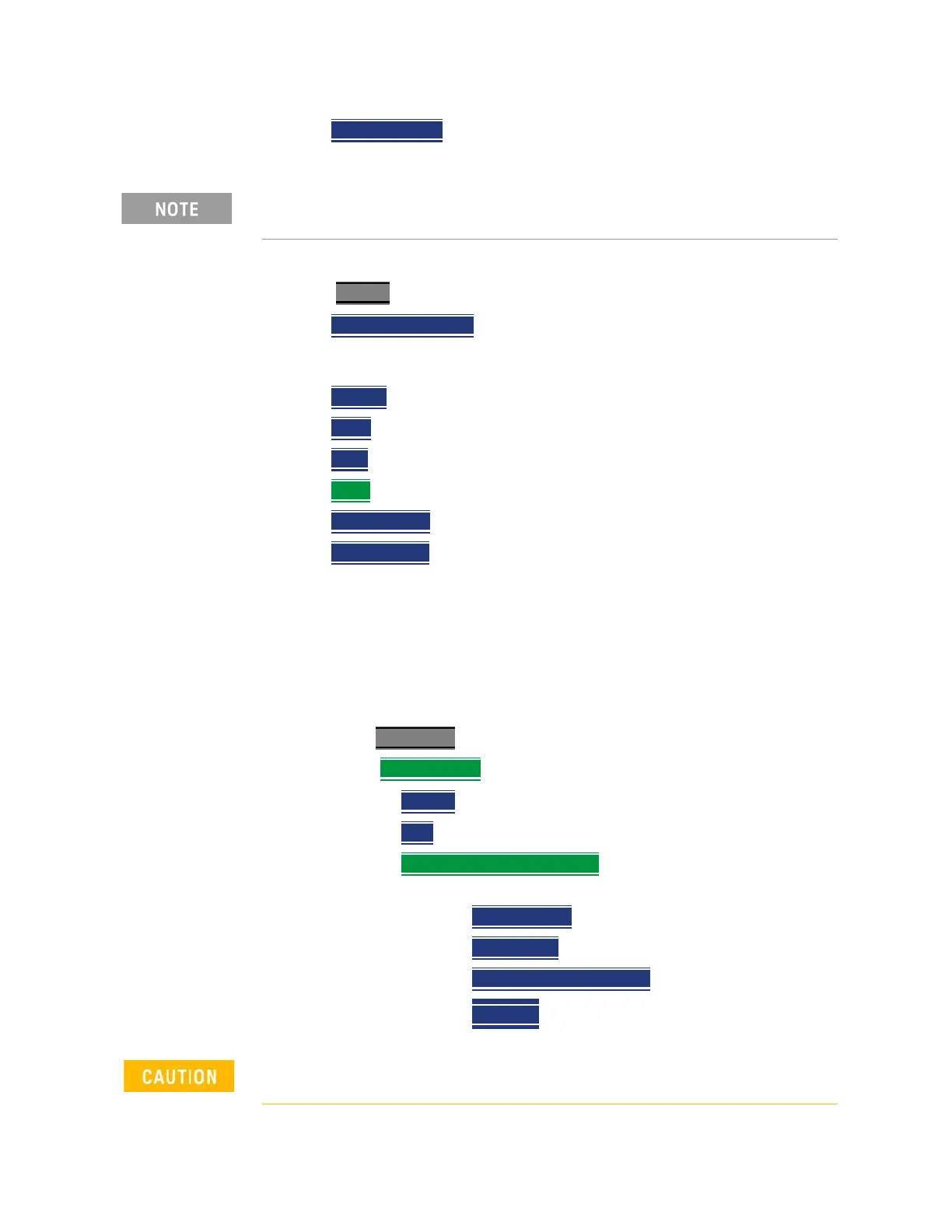
7. User markers to identify azimuth and elevations settings:
Select Marker
–choose:
— Marker 1 2 3 4 5 6
– You can set up to six markers. The OFF,
Normal, Delta, or Peak softkey is black to indicate the current setting
of each marker.
— Normal
displays a marker.
— Delta
displays a marker relative to another active marker.
— Peak
displays a marker on the peak point of the displayed trace.
— More
– choose.
— Marker Trace
– You can set up to four traces.
— Marker Table
– Enable or disable the marker table that displays the
current markers and their values.
Learn more about markers. Refer to the Chapter 28, “Data Analysis
Features.”.
See also Figure 5 on page 336.
8. Enable the Data Logging settings:
— Press Measure 1
— To set Data Logging
—choose:
— Record
or
— Play
or
— Save Recall Rec-Playback
(If you have previously stored
data recordings.)
——Save Log File
or
——Recall Logs
or
——User Folder Def System
(Default = Default) or
——File Type
(Default = KML) CVS or DREC
If after making the setting changes in the steps below, no data is
displayed, refer to “Troubleshooting” on page 364.
Spectrum information is not recorded. Only the TableChart data are saved.
See “How to Record” on page 360.

 Loading...


