TINPut A trigger input pin can be selected as the source for measurement and transient
trigger signals. See TRIGger:ACQuire:SOURce and TRIGger:TRANsient:SOURce
TOUTput A trigger output pin will generate output triggers from any subsystem that has
been configured to output trigger signals.
Common Applies only to pin 8. Connected to ground.
In addition to the configurable pin functions, the signal polarity (Positive or Negative) for each pin is
also configurable. For level signals, POSitive indicates a voltage high at the pin. NEGative indicates a
voltage low at the pin. For edge signals, POSitive means a rising edge and NEGative means a falling
edge.
Bi-Directional Digital I/O
Each of the seven pins can be configured as general purpose bi-directional digital inputs and outputs.
The polarity of the pins can also be configured. Pin 8 is the signal common for the digital I/O pins. Data
is programmed according to the following bit assignments:
Pin 7 6 5 4 3 2 1
BitWeight 6 (msb) 5 4 3 2 1 0 (lsb)
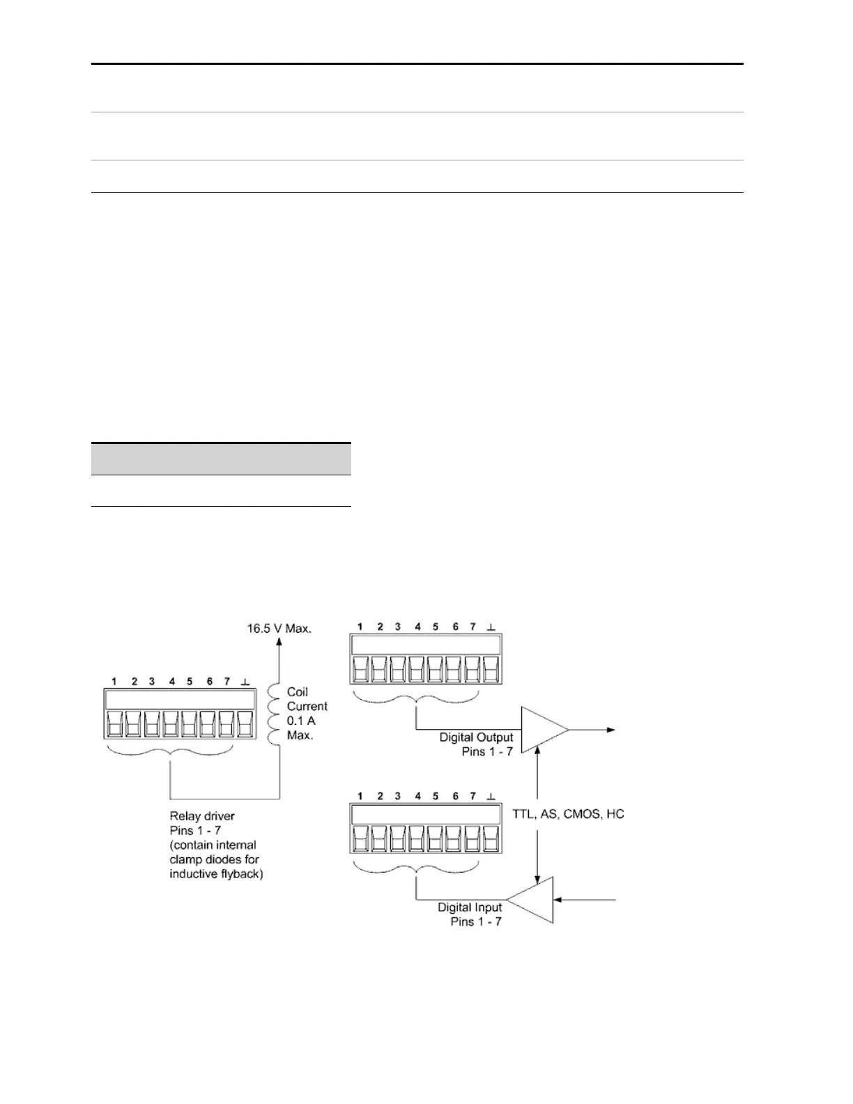
The digital I/O pin can be used to control both relay circuits as well as digital interface circuits. The
following figure illustrates typical relay circuits as well as digital interface circuit connections using the
digital I/O functions
4 Using the Advanced Power System
152 Keysight N6900/N7900 Series Operating and Service Guide

 Loading...


