1. Connect the instrument to the site LAN or to your computer using a LAN cable. The as-shipped
instrument LAN settings are configured to automatically obtain an IP address from the network
using a DHCP server (DHCP is set On). The DHCP server will register the instrument’s hostname
with the dynamic DNS server. The hostname as well as the IP address can then be used to com-
municate with the instrument. If you are using a private LAN, you can leave all LAN settings as
they are. Most Keysight products and most computers will automatically choose an IP address
using auto-IP if a DHCP server is not present. Each assigns itself an IP address from the block
169.254.nnn. The front panel Lan indicator will come on when the LAN port has been configured.
2. Use the Connection Expert utility of the Keysight IO Libraries Suite to add the APS models and
verify a connection. To add the instrument, you can request the Connection Expert to discover the
instrument. If the instrument cannot be found, add the instrument using the instrument’s host-
name or IP address.
3. You can now use Interactive IO within the Connection Expert to communicate with your instru-
ment, or you can program your instrument using the various programming environments. You can
also use the Web browser on your computer to communicate with the instrument as described
under Using the Web Interface.
Digital Port Connections
It is good engineering practice to twist and shield all signal wires to and from the
digital connector. If shielded wire is used, connect only one end of the shield to
chassis ground to prevent ground loops.
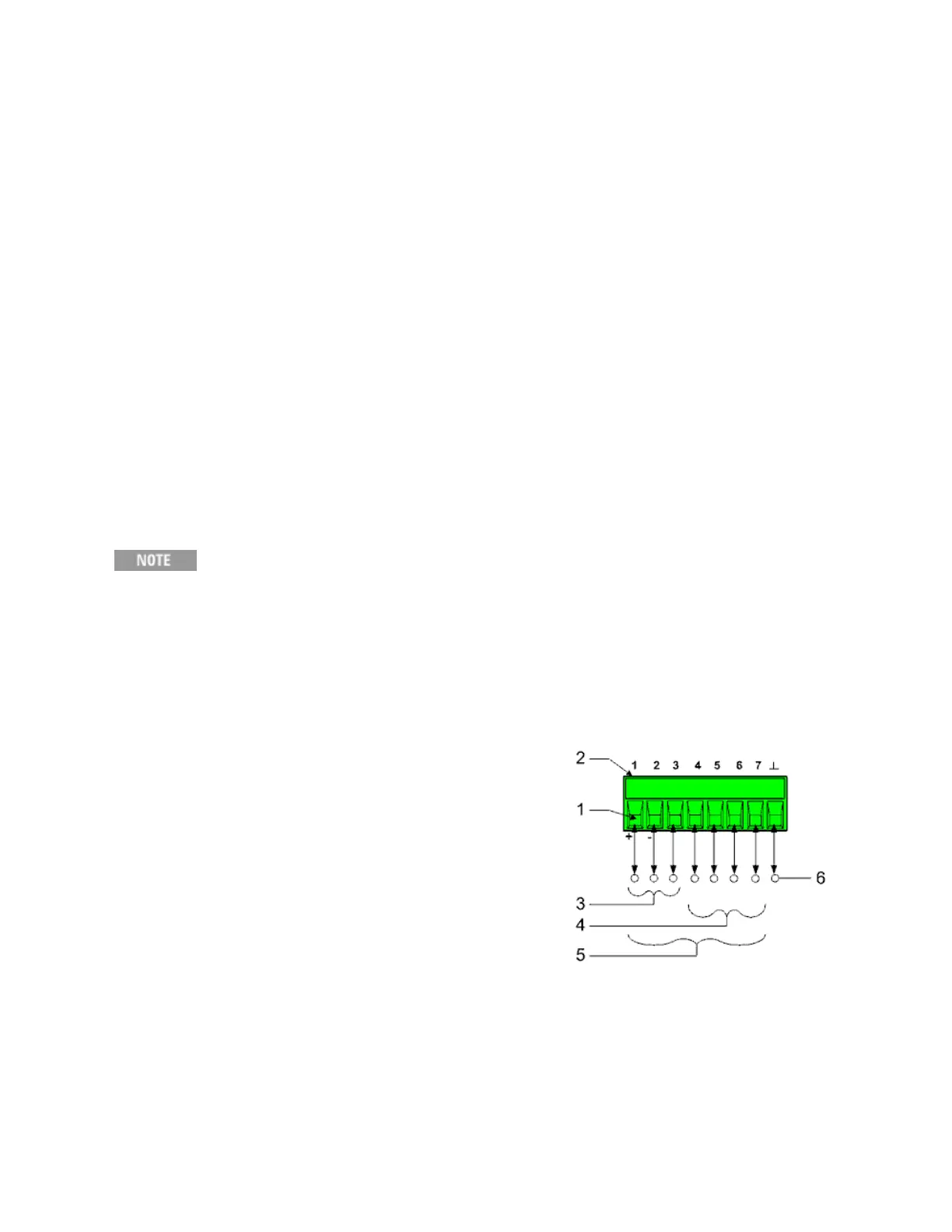
An 8-pin connector and a quick-disconnect connector plug are provided for accessing the digital port
functions. Disconnect the connector plug to make your wire connections. The connector plug accepts
wires sizes from AWG 14 (1.5 mm
2
) to AWG 28 (0.14 mm
2
). Wire sizes smaller than AWG 24 (0.25
mm
2
) are not recommended. Strip wire insulation back 7 mm.
1. Insert wires
2. Tighten screws
3. Fault/Inhibit configurable pins (observe INH polarity)
4. Output Couple configurable pins
5. Digital IO-configurable or Expression-configurable pins
6. Signal common
Information on using the digital port is found under Programming the Digital Port. The electrical
characteristics are described under Common Characteristics.
2 Installing the Instrument
88 Keysight N6900/N7900 Series Operating and Service Guide

 Loading...


