Priority Mode Tutorial
Voltage Priority
In voltage priority mode the output is controlled by a constant-voltage feedback loop, which maintains
the output voltage at its programmed setting as long as the load current remains within the positive or
negative current limit settings. Voltage priority mode is best suited for use with resistive or high
impedance loads, and loads that are sensitive to voltage overshoots. Do not use voltage priority mode
with low-impedance sources such as batteries, power supplies, or large charged capacitors.
In voltage priority mode, the output voltage should be programmed to the desired value. A positive
and negative current limit value should also be set. The current limit should always be set to a value
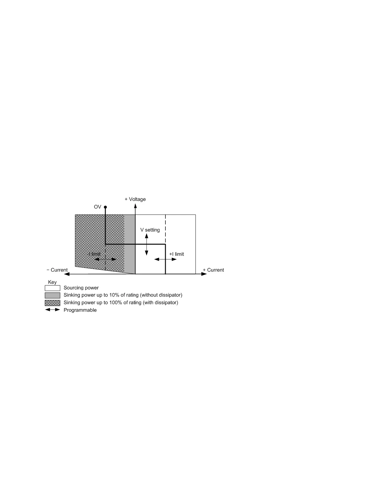
that is greater than the actual output current requirement of the external load. The following figure
shows the voltage priority operating locus of the output. The area in the white quadrants shows the
output as a source (sourcing power). The area in the shaded quadrants shows the output as a load
(sinking power).
The heavy solid line illustrates the locus of possible operating points as a function of the output load.
As shown by the horizontal portion of the line, the output voltage remains regulated at its
programmed setting as long as the load current remains within the positive or negative current limit
setting. A CV (constant voltage) status flag indicates that the output voltage is being regulated and
the output current is within its limit settings.
When the output current reaches either the positive or negative current limit, the unit no longer
operates in constant voltage mode and the output voltage is no longer held constant. Instead, the
power supply will now regulate the output current at its current limit setting. Either a LIM+ (positive
current limit), or LIM– (negative current limit) status flag is set to indicate that a current limit has been
reached. These conditions are annunciated by CL+ or CL- on the front panel.
As shown by the vertical portions of the load line, the output voltage may continue to increase in the
positive direction or decrease in the negative direction as current is forced into or pulled out of the unit.
When the output voltage exceeds the over-voltage protection setting, the output will shut down, the
output relays will open, and the OV status bit will be set.
4 Using the Advanced Power System
180 Keysight N6900/N7900 Series Operating and Service Guide

 Loading...


