112 General Maintenance
Removing Fixed Chute
To remove the fixed chute apply the following procedure:
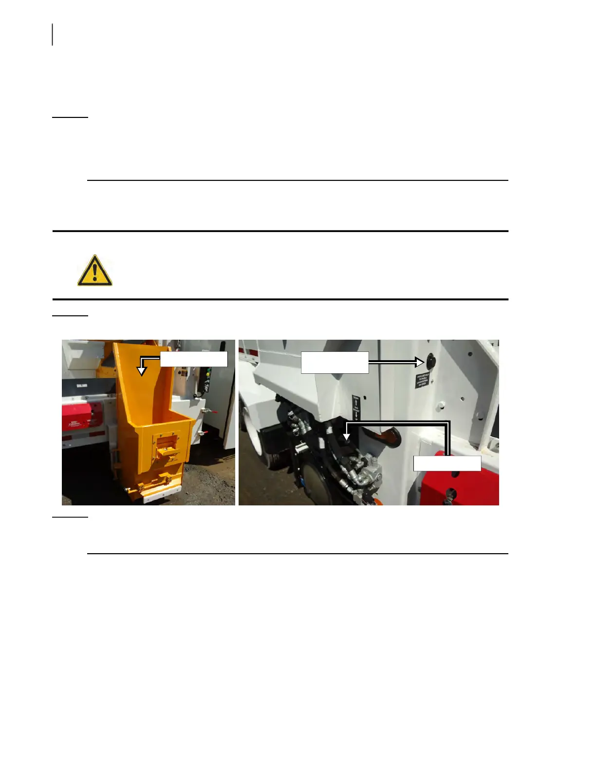
NOTE: While it is possible to remove the fixed chute altogether, as a single part, we recommend
removing it by taking out its main components one at a time. The fixed chute is comprised of
five main components: the chute itself, the deflector, the chute cap, the upper reinforcement
and the chute support (see Figure 3-138).
1. Start the truck and engage the hydraulic pump.
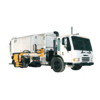
2. Using the tipper lever near the hopper, fully lower the SSO tipper (see Figure 3-139).
Figure 3-139
SSO tipper and lever
NOTE: If the tipper lever is combined with a deadman’s switch (see Figure 3-139), the latter must be
pressed to enable the lever.
3. Turn OFF the hydraulic pump and stop the engine.
4. Lock out and tag out the vehicle (see Locking Out and Tagging Out the Vehicle on page 14).
5. Remove the upper reinforcement by removing the two carriage bolts that hold it in place.
6. Remove the chute (see Figure 3-138).
This is the main part of the chute assembly. 9 bolts are to be taken out to remove it.
7. Remove the chute deflector (see Figure 3-138).
6 carriage bolts are to be taken out to remove that part.
8. Remove the chute cap (see Figure 3-138).
Caution!
Make sure no one is standing in the descent path of the tipper.
SSO Tipper
Deadman’s
switch
Tipper lever