292 Hydraulic System
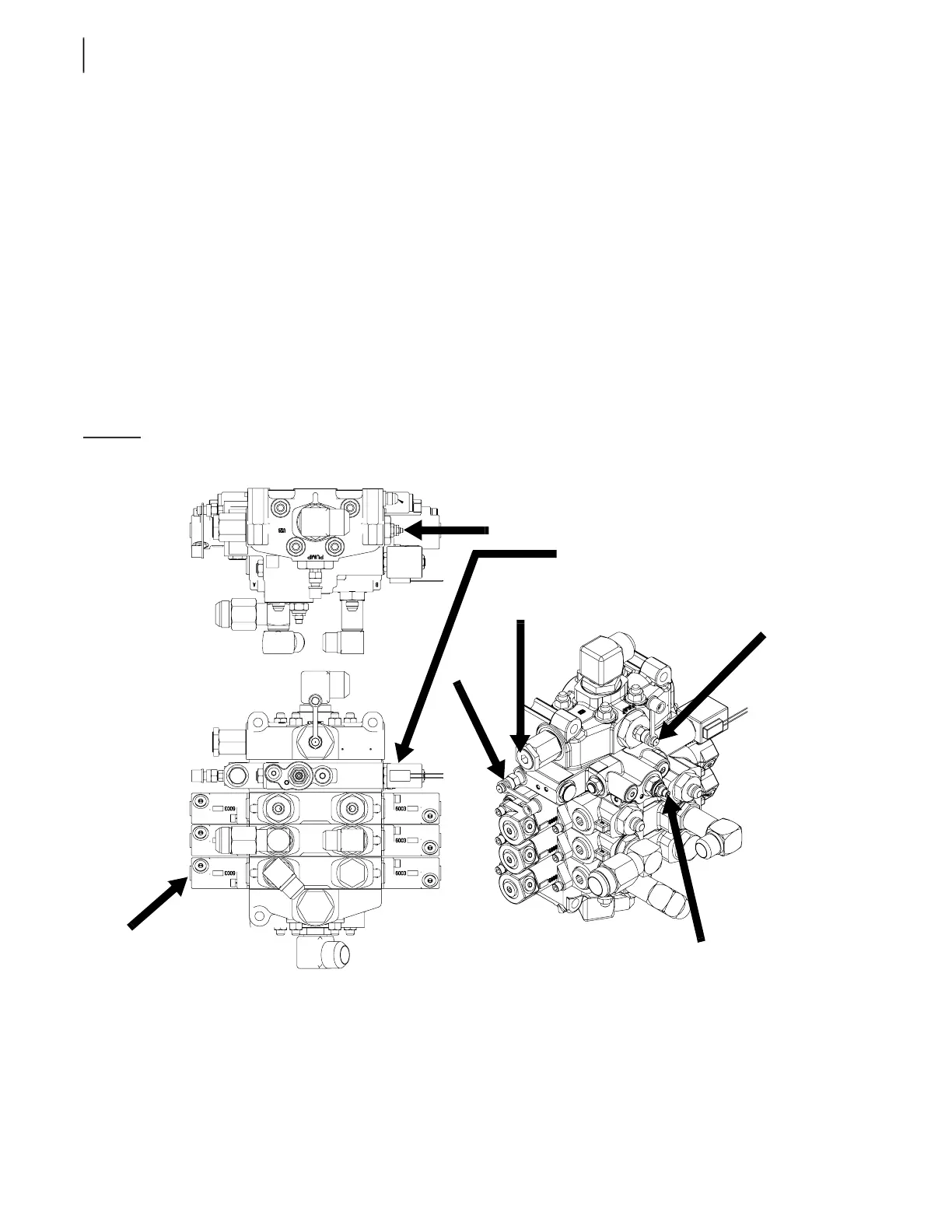
6. Disconnect the body-up coil (see C on Figure 5-35).
7. With the engine at idle, adjust the pilot generating relief valve (see A on Figure 5-35) to 420 PSI
(±20 PSI) while the Body Up function is activated. The valve adjustment screw is located on the
right-hand side of the valve section when facing it.
8. Reconnect the body-up coil.
9. Remove the pressure gauge from the inlet cover and install it on the maximum pilot pressure port
(see D on Figure 5-35).
10. Disconnect the packer extend proximity switch.
11. Activate the packer extend until it reaches the end of stroke.
12. Adjust the pressure reducing valve to 550 PSI (±20 PSI) using the adjustment screw located at
the front of the valve (see B on Figure 5-35).
13. Test the valve.
The valve should shift sharply.
Figure 5-35
Valves and ports
Adjusting Proportional Valve Pressure
EXPERT™ vehicles use an extra valve stack to control the arm and the chute (if equipped). This valve is
of the proportional type, meaning that the amount of flow coming out of it depends on the position of
the spool.
A
C (behind)
F (main relief)
E
B
D
This section, known as the utility sec-
tion, is fixed to an electro-hydraulic
valve only