Hydraulic System 297
6. Put the transmission in Neutral, start the engine and engage the hydraulic pump.
7. Adjust gripper pressure:
7 a. Install lever on the section of the valve that controls the gripper (see Figure 5-37).
7 b. Close the gripper using the lever you have just installed.
7 c. While maintaining the lever in its depressed position, adjust the relief valve of the “gripper
close” side of the valve section to 1200 PSI
1
(±50 PSI).
Screw or unscrew depending on the gauge reading.
7 d. Open the gripper using the lever and maintain the lever in its depressed position.
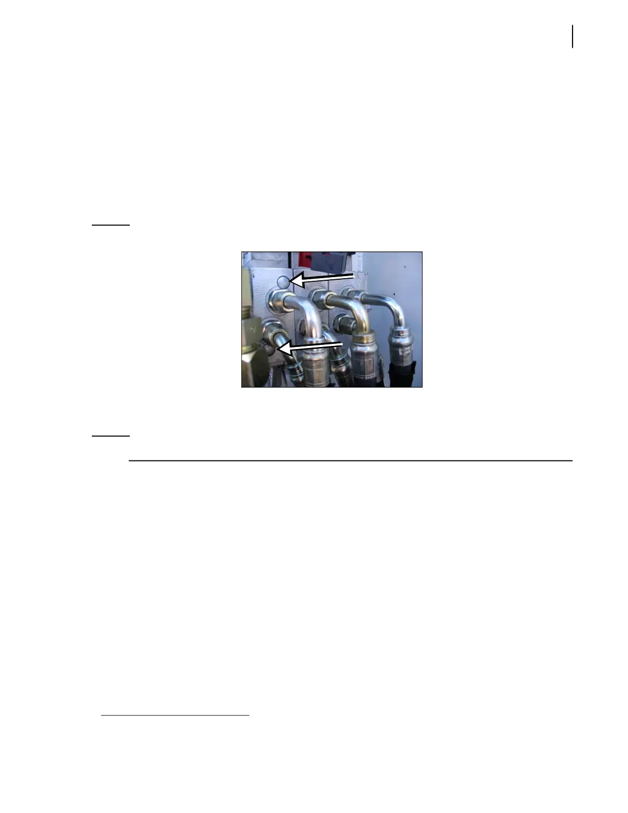
7 e. Adjust the pressure of the “gripper open” load/sense relief valve to 1200 PSI (±50 PSI).
Figure 5-41
Gripper load/sense relief valve
Adjusting Tipper Valve Pressure
NOTE: This task requires two people.
To adjust the working pressure of the tipper valve:
1. Connect a 0-4000 PSI gauge to the flow divider quick-connect coupler just above the main valve
(see Figure 5-42).
2. Start the engine and engage the hydraulic system (pump switch ON).
3. Activate the tipper manually with the control lever (see Figure 5-43) until it reaches its
uppermost position.
4. Keep the lever pulled down while your helper takes the pressure reading on the gauge.
5. Depending on the gauge reading, turn the adjustment screw (see Figure 5-43) clockwise or
counter-clockwise to set the pressure to 2000 PSI (±50 PSI).
6. Pull up the tipper lever to completely retract the tipper.
7. Keep the lever pulled up while your helper takes the pressure reading on the gauge.
8. Depending on the gauge reading, turn the adjustment screw (see Figure 5-43) clockwise or
counter-clockwise to set the pressure to 2000 PSI (±50 PSI).
1. Reference value varies according to use. This pressure can be adjusted according to customer’s needs.