288 Hydraulic System
Hydraulic Pressures
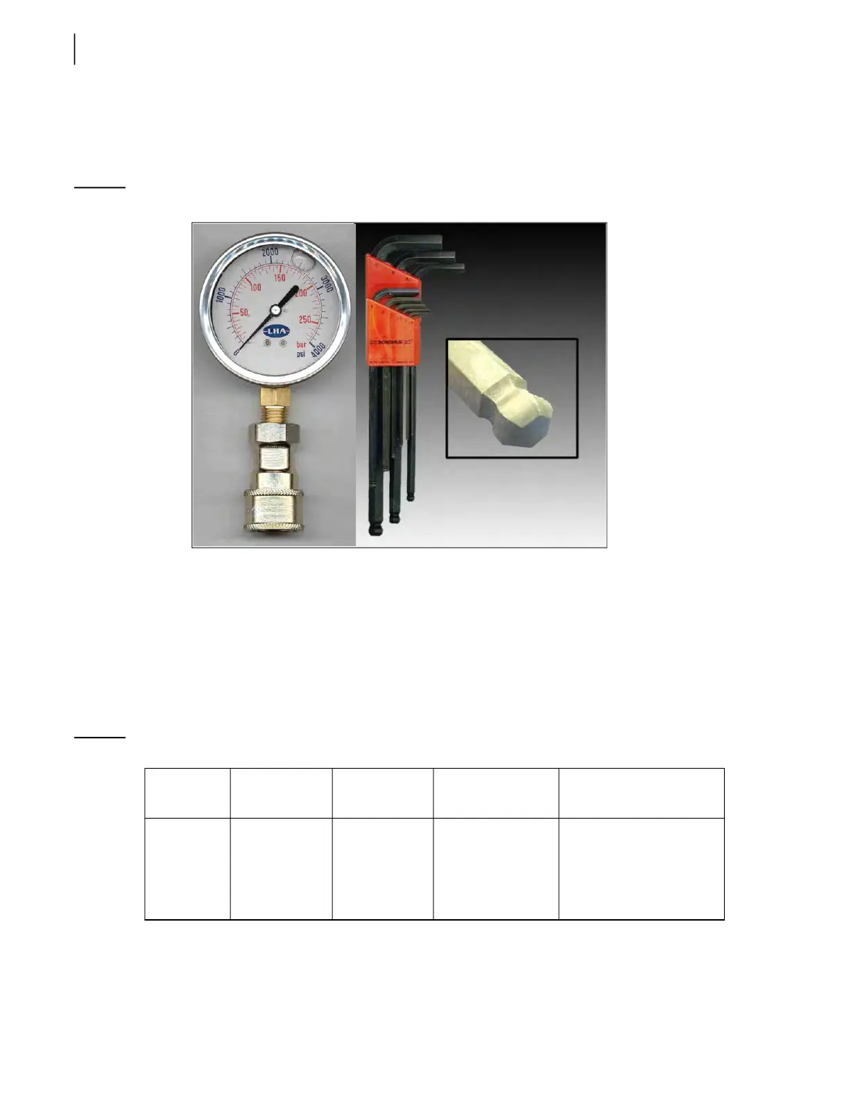
A 0–4000 PSI pressure gauge as well as a set of ball-end hex keys are required to adjust different
working pressures of the truck’s hydraulic system (see Figure 5-30).
Figure 5-30
Pressure gauge and ball-end hex key
Adjusting Vane Pump Relief Valves (if equipped)
The body and arm sections of the dual vane pump may have their own relief valve on the dump valve;
one located on the pump, the other on the chassis. Adjustment of vane pump relief valves must be
done before adjusting the relief valve of the directional control valve.
The following pressure chart gives the proper adjustment pressure for body functions. Use this chart
to adjust the relief valve for the body vane pump. For arm functions, see Adjusting the Arm Vane Pump
Relief Valve on page 393.
Table 1 Pressure chart
Pump Chassis
Cylinder bore
(packer)
Main relief
pressure (±50 PSI)
Dump valve pressure
(if equipped) (±50 PSI)
Vane pump 6×4
(tandem axle)
4×2
(single axle)
4 inches
4 inches
3,000 PSI at idle
2,000 PSI at idle
3,300 PSI at idle
2,200 PSI at idle