296 Hydraulic System
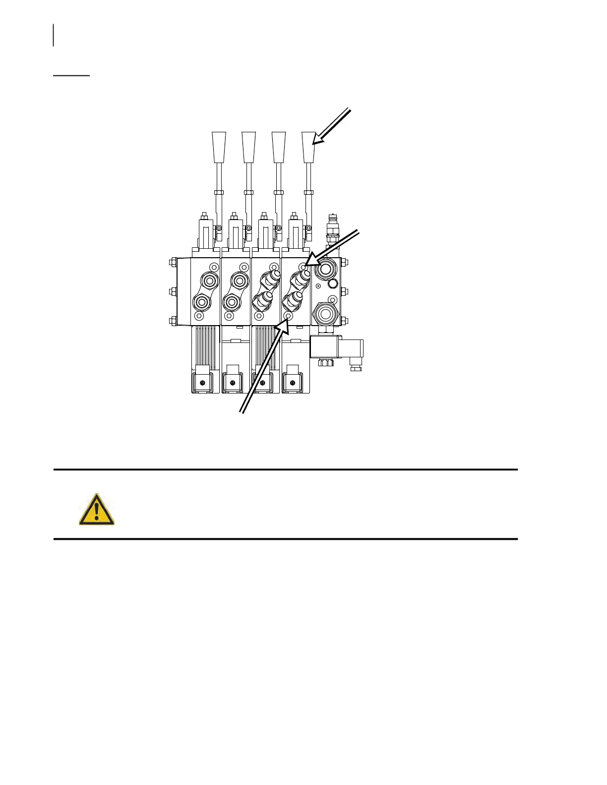
Figure 5-40
Control levers
Adjusting Gripper Pressure
See Figure 5-37 to locate the section of the proportional valve that controls the gripper. The section is
equipped with a built-in relief valve that allows gripper pressure adjustment.
To adjust the gripper built-in relief valve:
1. Lock out and tag out the vehicle (see Locking Out and Tagging Out the Vehicle on page 14).
2. Secure the area around the path of the arm with barrier tape or barricades.
3. Move the manual levers back and forth to release any residual pressure.
4. Make sure that all hoses are tight and not leaking.
5. Connect a pressure gauge (0–4000 PSI) to the quick-connect coupler on the proportional valve
(see Figure 5-38).
Danger!
Do not stand directly in the path of the arm while carrying out these adjustments.
Chute control
lever (also one in
the cab)
Work port relief
(chute right)
Work port relief
(chute left)