Electrical System 313
Adjusting and Repairing Electrical Components
The required electrical system adjustments include:
Fuses and circuit breakers
Limit and proximity switches
Fuses and Circuit Breakers
Power for the electrical system on board the EXPERT™ is protected by a set of fuses and circuit
breakers.
Fuses
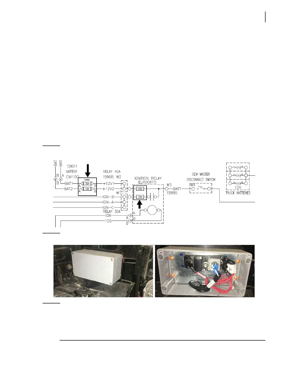
Two fuses (30A and 40A), which are located inside the ignition relay box (see Figure 6-3), are used to
protect the Labrie electrical system.
The 40A circuit is subdivided into 2 secondary circuits (10A and 30A) which are protected by in-line
fuses.
Figure 6-1
Circuit schematic - Ignition relay box
Figure 6-2
Ignition relay box (with/without cover)
NOTE: When a fuse blows, always replace it with a fuse of the same kind and same amperage. Fuses
30A and 40A are protected by a plastic cover (see Figure 6-3). Just remove that plastic cover to
gain access to these fuses. For fuses 10A and 30A found just outside the relay box (see Figure
6-4), they are also protected by a plastic cover that needs to be removed to gain access to the
fuse. Always check amperage before attempting to replace a dead fuse.