General Maintenance 219
IMPORTANT: All limit switches MUST be working at all times. Otherwise, the operator may not be aware that the
arm is not fully retracted or that the gripper is open or closed. This may cause an accident, injuries or
property damages.
Adjusting Chute Limit Switches (Co-Mingle Units)
The chute must be tilted completely on one side or the other to allow the crusher panel or the
automated arm to move normally. If the chute is not completely tilted on either side, no movement of
the crusher panel or the automated arm should occur.
When the chute is completely tilted on either side, it triggers a limit switch. Only then, the automatic
arm or the crusher panel can move normally. There are two chute limit switches: one for the left-hand
side end-of-stroke of the chute, the other for the right-hand side end-of-stroke of the chute. For the
crusher panel or the automated arm to work normally, one of these limit switches must be triggered.
NOTE: In the case of a two-crusher panel setup, only one panel will move and this panel is dependent
on which side the chute is resting. In the case of a one-crusher panel setup, the panel will only
move if the chute is on the opposite side from it.
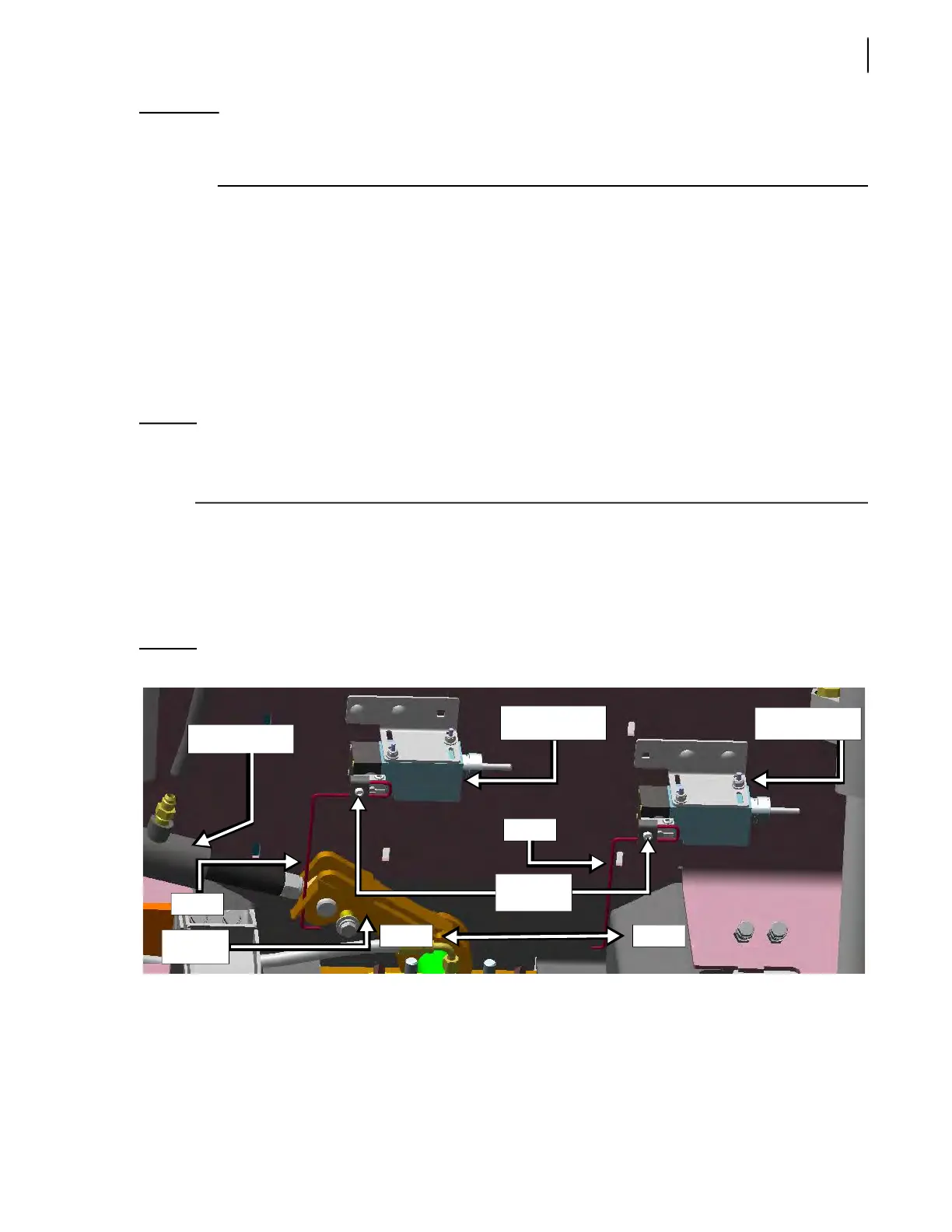
Both limit switches are located near the chute cylinder (see Figure 3-315). The right-hand side limit
switch is used to detect the chute when completely tilted on the right side of the hopper, while the
left-hand side limit switch is used to detect the chute when completely tilted on the left side of the
hopper.
If either limit switch cannot detect the completely tilted chute, it will have to be adjusted.
Figure 3-315
Chute limit switches
To adjust the right-/left-hand side chute limit switch:
1. Remove the crusher panel deflector, if equipped (see Figure 3-316).
2. Remove both protective panels that are fixed to the rear hopper wall (see Figure 3-317). To do
so:
2 a. Start the truck and engage the hydraulic pump.
Chute cylinder
RHS chute limit
switch
LHS chute limit
switch
Rod
Adjustment
screws
To leftTo right
Rod
Chute
lever