Hydraulic System 291
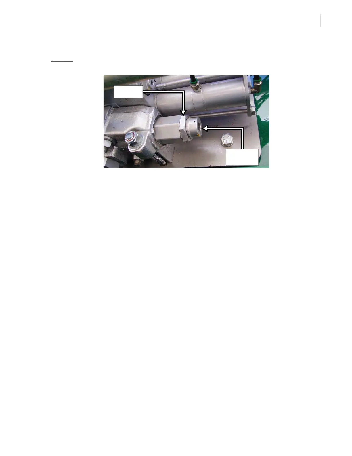
6. Adjust the directional control relief valve as needed by loosening the locknut and by turning the
adjustment screw (see Figure 5-34).
Figure 5-34
Relief valve
Using a ½” Allen key, turn the adjustment screw clockwise to increase pressure or counter-
clockwise to reduce pressure.
Use a 1½” key to screw/unscrew the locknut.
7. Reconnect the packer extend proximity switch.
Adjusting Body Relief Valve (Electro-Hydraulic Valve)
To adjust the body relief valve:
1. Once the body vane pump relief valve is adjusted, back out the main relief (see F on Figure 5-35).
2. Install the pressure gauge on the valve inlet cover (see E on Figure 5-35).
3. Disconnect the packer extend proximity switch.
4. Activate the packer extend until it reaches the end of stroke.
5. If no reading is shown, adjust the utility section of the electric valve (see page 291).
6. Set the pressure to 2000 PSI at idle for a single axle or to 3000 PSI at idle for a tandem axle (see
Pressure chart on page 288).
Adjusting Utility Section (Optional Electric Valve only)
To adjust the utility section:
1. Disconnect the tailgate solenoid.
2. Turn ON the pump.
3. Press the TAILGATE DOWN switch on the control panel.
4. Connect a 0–600 PSI pressure gauge to the quick-connect coupler on the inlet cover (see E on
Figure 5-35).
5. Back out the pilot generating relief valve (see A on Figure 5-35) and the pressure reducing valve
(see B on Figure 5-35).
Locknut
Adjustment
screw