Lifting Arms 383
Main Relief Valve Adjustment Procedure:
1. Remove any residual hydraulic pressure in the system by moving the levers back and forth.
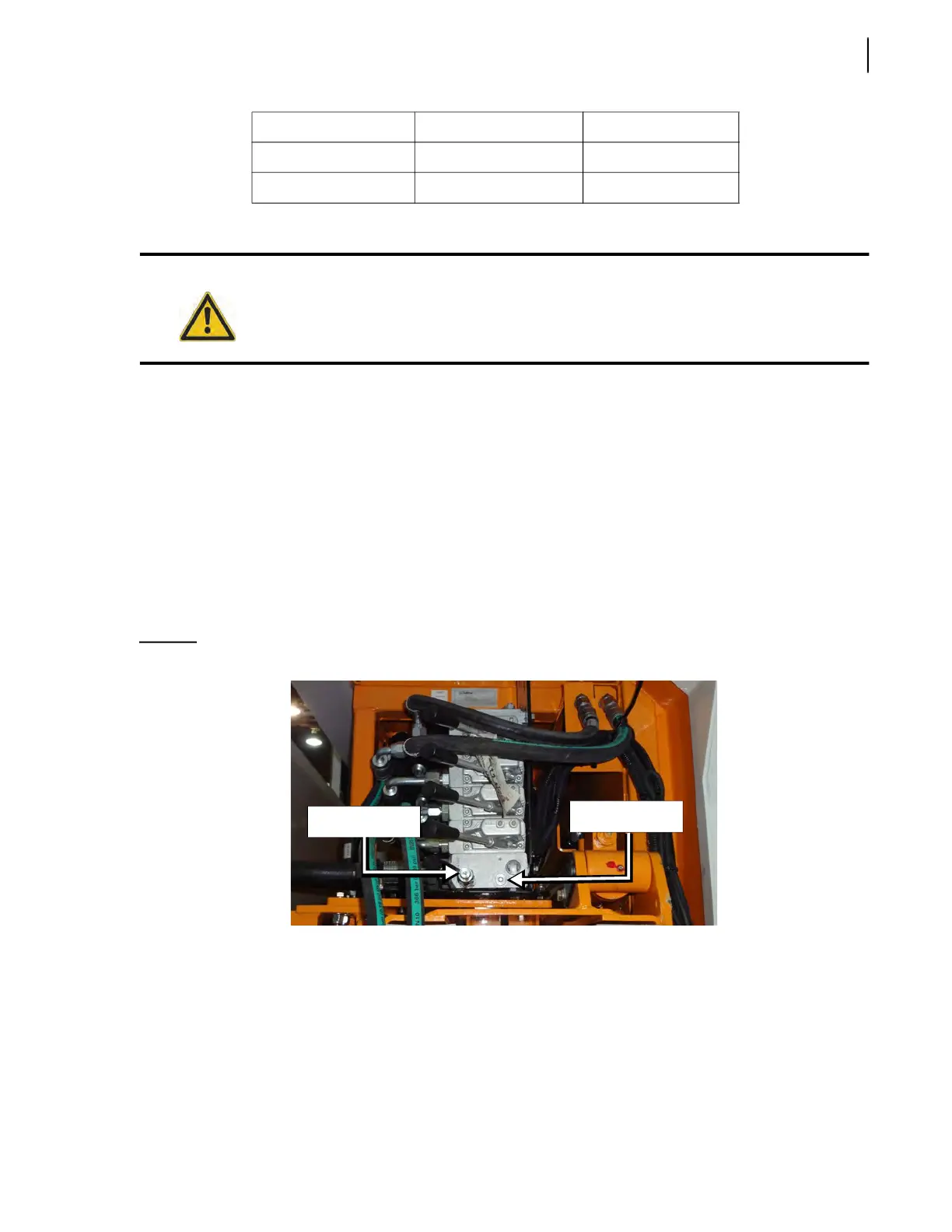
2. Connect a 0-4000 PSI gauge to the quick coupler located on the valve (see Figure 10-7).
3. Make sure the transmission is in neutral.
4. Start the engine.
5. Engage the hydraulic system.
6. Retract and maintain the arm to the end of its stroke in order to make the pressure rise on the
gauge.
7. Adjust the main relief valve to 2000 PSI using the adjustment screw (see Figure 10-7). Turn the
hex key clockwise or counterclockwise to adjust the pressure properly.
Figure 10-7
Main relief valve
Arm Functions Adjustment Procedure
The operating pressure of the arm (retract/extend) and the gripper (up/down) depends on the
pressure that is generated by the hydraulic system. No adjustment is required for these functions.
Only the gripper closing and opening pressures require adjustment to prevent crushing roller carts
and damaging the gripper. Apply the following procedure to adjust the relief valves on the gripper
section (refer to Pressure Adjustment Table on page 382).
Arm Down System Pressure 2.5 - 3.0
Gripper Close 1200 PSI (±50 PSI) 1.0 - 1.5
Gripper Open 1200 PSI (±50 PSI) 1.3 - 1.8
a. Cycle time is defined as the time required for a function to complete a full back and forth movement.
Cycle time may vary depending on weather conditions
Warning!
Before making any adjustments, secure the arm working area using safety tape or barricades.
Quick coupler
Adjustment
screw