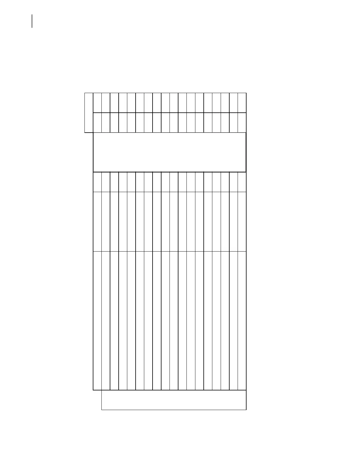
302 Hydraulic System
Pressure and Cycle Time Charts - EXPERT™
Chart 1
r
m
min max
Parker
700 rpm n/a n/a
VG-35
700 rpm n/a n/a
circuit
700 rpm n/a n/a
700 rpm n/a n/a
700 rpm 45,0 55,0
700 rpm 25,0 40,0
700 rpm n/a n/a
700 rpm n/a n/a
700 rpm n/a n/a
700 rpm n/a n/a
1200 rpm 10,0 12,0
PL14-IT42
PL14-IT42
pressure settingfonction Labrie procedure
PL14-IT20
PL14-IT20
PL14-IT39
main relief valve chassis 4x2
main relief valve chassis 4x2 with tag and 6x4
dump valve R5P (if adjustable) chassis 4x2
2000 ± 50 psi
PL14-IT39
system pressure
1500 ± 50 psi
3000 ± 50 psi
2200 ± 50 psi
3300 ± 50 psi
1700 psi ± 100 (non-adjustable)
n/a single acting cylinder
dump valve R5P (if adjustable) 4x2 with tag and 6x4
body hoist up
body hoist down
packer extend
packer retract
relief setting on regeneration valve chassis 4x2 (before 2014, programed in IFM
module after
relief setting on regeneration valve chassis 4x2 with tag and 6x4 (before 2014,
ro
ramed in IFM module after
packer complete cycle without regeneration
packer complete cycle with regeneration
,
,
700 rpm n/a n/a
max rpm n/a n/a
700 rpm 2,0 4,0
700 rpm 1,0 3,0
700 rpm n/a n/a
PL14-IT20
PL14-IT20550 ± 20 psi
system pressure with power bleed
system pressure with velocity fuse
to drain
600 ± 50 psicrusher panel holding valve (to keep up)
pilot generating relief valve on utility section, EH valve only
pressure reducing valve on utility section, EH valve only
crusher panel up
crusher panel down