384 Lifting Arms
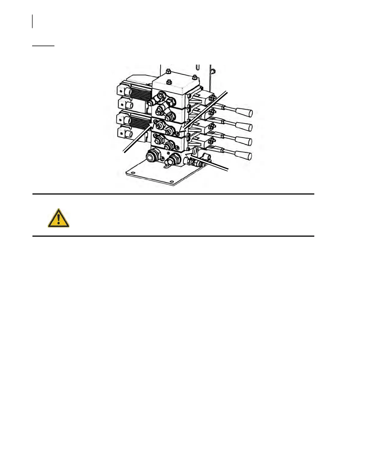
Figure 10-8
Gripper relief adjustment screws
Gripper Closing/Opening Pressure Adjustment Procedure:
1. Secure the arm working area using safety tape or barricades.
2. Remove any residual hydraulic pressure in the system by moving the levers back and forth.
3. Connect a 0-4000 PSI pressure gauge (see Figure 8-3) to the quick coupler located on the
hydraulic valve.
4. Put the transmission in neutral.
5. Start the engine.
6. Engage the hydraulic pump.
7. Close the gripper using the appropriate lever on the valve (see Figure 10-5).
8. Adjust the relief valve for the “gripper close” side of the valve section to 1200 PSI (screw or
unscrew depending on the gauge reading).
9. Open the gripper and adjust the relief valve for the “gripper open” side of the valve section to
1200 PSI (screw or unscrew depending on the gauge reading).
Arm/Gripper Speed Adjustment
The arm/gripper speed depends on the amount of hydraulic fluid that is being sent to the arm
cylinder. The valve spool can let through up to 28 gallons of hydraulic oil per minute (GPM),
depending on the valve section. The flow is also limited by a mechanical movement restrictor (or
stopper).
Warning!
Do not stand directly in the path of the arm while carrying out these adjustments.
“Gripper open” relief
adjustment screw
“Gripper close”
relief adjustment
screw
Main relief valve