Lifting Arms 395
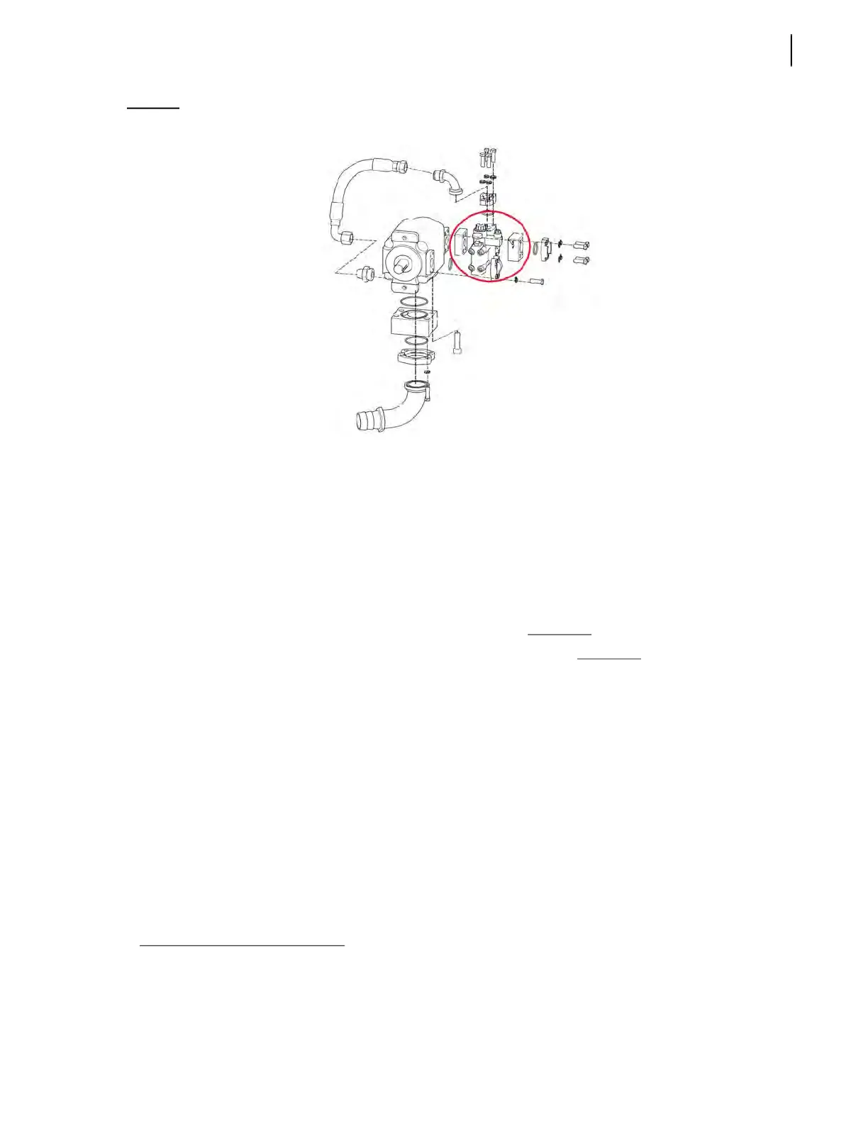
Figure 10-21
Dump valve and orifice block
7. Open the ball valve (or shut-off valve) that was closed in step 3.
8. Start the truck.
Note that the second the truck is running there will be hydraulic fluid going to the arm valve
assembly. The Emergency Stop will not stop the hydraulics from working, only turning the truck
off will. Ensure everyone, and everything, is out of the way of the arm in case it moves on its own
should there be an electrical short or a catastrophic failure internal to the valve assembly.
Now that the arm dump valve is bypassed, we will be able to identify if the arm pump or arm
dump valve is faulty. Simply go to the arm valve assembly and operate the arm manually.
• If the cycle times and pressures are correct, then the arm dump
valve is faulty.
• If the cycle times and pressures are still not correct, then the arm pump
is faulty.
9. Assembly in the opposite of disassembly.
Proportional Coil Signals
The up/down and in/out movements of the HELPING-HAND™ arm depend on a type of signals that
varies according to the position of the joystick. Those signals are called proportional signals, meaning
that the more you move the joystick from its neutral position, the faster the arm moves, whether up-
and-down or in-and-out.
A movement of the joystick sends a signal via the CAN bus wire to the PWM adapter. The frequency
of this signal is expressed in Hertz. The PWM adapter automatically converts it to a voltage
proportional to the duty cycle
1
. The new signal is then forwarded directly via the signal wire to the
proportional coil located on the arm valve.
1. Measured in percentage, the duty cycle represents the percentage of time a signal is ON over a period of time. If a signal is ON 50% of the
time and OFF 50% of the time, the signal has a duty cycle of 50%. If this signal is ON more than 50% of the time or less than 50% of the time
over a specific interval, the duty cycle of the signal will vary accordingly, more or less than 50%. The duty cycle is a concept that is part of
the pulse-width modulation (or PWM) which relates to a type of digital signal.