Toe-In
Toe measurement is the angle between the vehicle
center line and the tire. The front wheels of the vehicle
should be adjusted for a slight inward alignment of the
forward edge of the wheels so they are closer together
at the front than at the back of the vehicle. This toe-in
adjustment improves steering and equalizes tire wear.
To make the toe-in adjustment:
1. Park the machine on level ground and straighten the
front wheels vertical with the grader boom frame.
2. Lower the moldboard enough to raise the front
wheels slightly, then block front axle.
3. Engage the park brake and turn off the engine.
4. Measure and mark the center of both front tires with
chalk or white marker.
5. Measure the distance between the marks on the
front tires.
6. Rotate tires so marks are at the rear and measure
the distance between the marks.
7. If the difference between the tire marks measured
front and rear is more or less than 1/8-inch (3.2 mm),
adjust the front tires by loosening the tie-rod jam
nuts. (Figure 5-7) Turn the wheels completely left
and right, checking for an obstructions or damaged
parts.
Tie Rods
Figure 5-7. Tie Rods
Park Brake (Rear Bogie Axle)
The park brake is used to hold the grader in position
while parked and may need adjustment due to wear and
extensive use. If you notice any slippage, adjustment is
needed.
Adjustment components are located on the top of
both sides of the front bogie axle. Use the following
procedure if the park brake needs adjustment:
1. Park the machine on a level surface, shut down the
engine and engage the park brake.
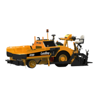
• Use the brake bleeder port to relieve pressure if
needed. (Figure 5-8)
Brake
Bleeder
Adjuster
Screw
Front View
Figure 5-8. Park Brake Adjustment (Right Side
Shown)
2. The park brake adjustment screw is located in the
cavity just below and to the right or left (depending
on the side adjusting) of the bleeder port as shown
in Figure 5-8. Use a at-head screwdriver to
carefully remove the cavity cover.
3. Using a 13 mm wrench, loosen and remove the
bolt and retaining clip, which exposes the adjuster
screw.
4. Using a 14 mm wrench, turn the adjuster screw
counterclockwise until snug (5 - 6 ft lb), then mark a
at side of the adjuster screw.
5. Turn the adjuster screw clockwise ve (5) complete
turns.
6. Reinstall the bolt and retainer clip.
7. Repeat Steps 2 - 6 on the other side.
Maintenance
LeeBoy 685D Motor Grader5-12