Parameter Name / value range / [default seng] Info
0x291A
(P223.00)
Deceleraon me 2
(Decelerat.me 2)
0.0 ... [5.0] ... 3600.0 s
Deceleraon me 2 for the operang mode "MS: Velocity mode".
•
The deceleraon me set refers to the deceleraon from the maxi-
mum frequency set to standsll. In the case of a lower actual fre-
quency, the actual deceleraon me is reduced accordingly.
•
The deceleraon me 2 is acve if the frequency setpoint (absolute
value) ≥ auto change-over threshold 0x291B (P224.00) or the trigger
assigned to the funcon "Acvate ramp 2" in 0x2631:039 (P400.39) =
TRUE.
•
The deceleraon me 2 is also used for changing the MOP setpoint
generated by the "motor potenometer" funcon.
•
Seng is not eecve in the operang mode 0x6060 (P301.00) =
"CiA: Velocity mode [2]". 4Device prole CiA 402 ^ 469
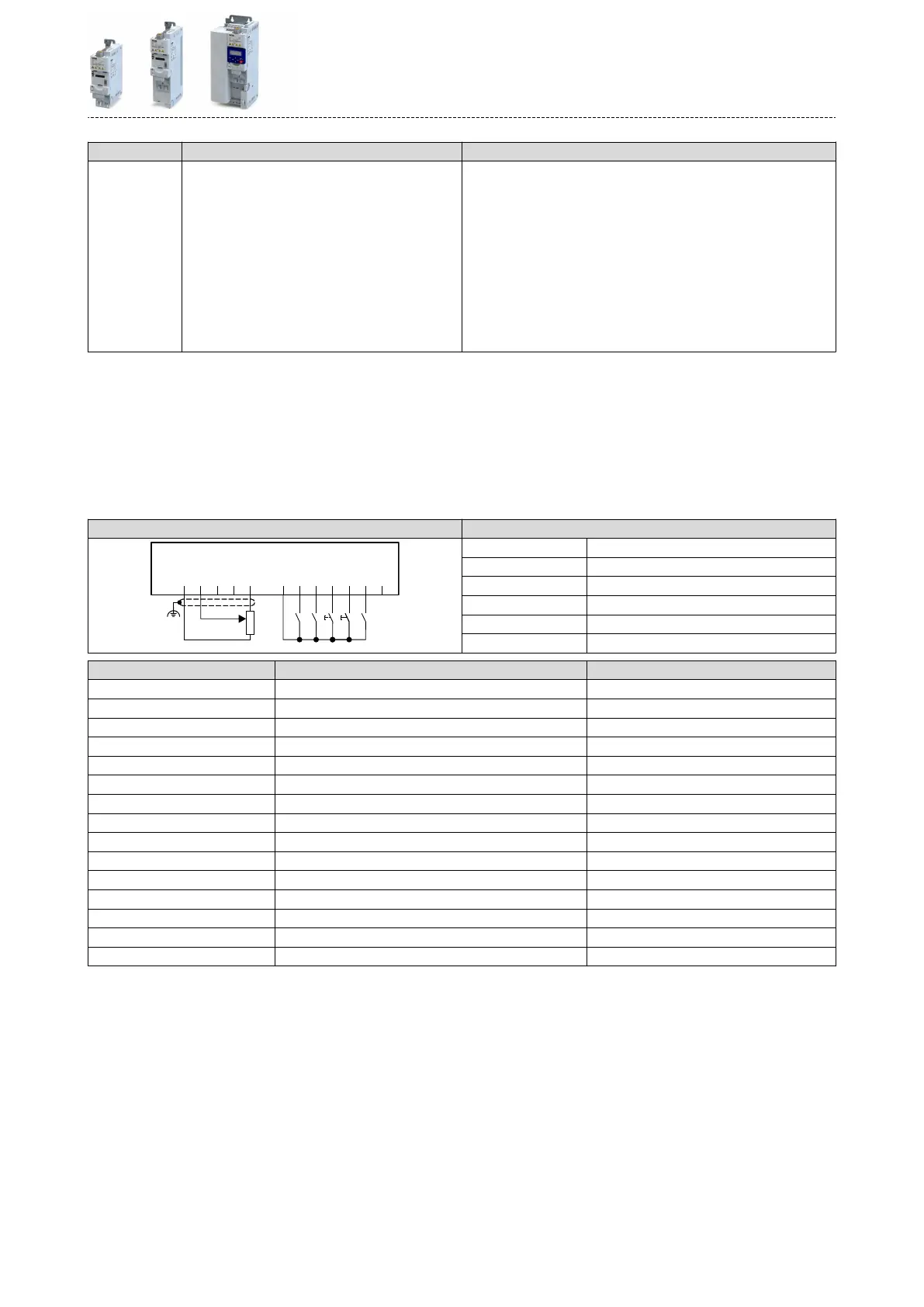
Example for operang mode
•
The analog input 1 is set as standard setpoint source.
•
Switch S1 starts the motor in forward direcon of rotaon. Switch S1 in the inial posion
stops the motor again.
•
Switch S2 acvates the motor potenometer as setpoint source. The MOP setpoint can
then be increased via buon S3 and reduced via buon S4. If both buons are pressed at
the same me, the MOP setpoint remains unchanged.
•
Switch S5 switches the direcon of rotaon.
Connecon plan funcon
GND
AI1
AI2
AO1
10V
24V
DI1
DI2
DI3
DI4
DI5
DO1
X3
S1 S2 S4 S5S3 S4
1k ...10k
0 ... 10 V
R1
Potenometer R1 Frequency setpoint selecon
Switch S1 Run
Switch S2 Acvate MOP setpoint
Buon S3 MOP setpoint up
Buon S4 MOP setpoint down
Switch S5 Reverse rotaonal direcon
Parameter Name Seng for this example
0x2631:001 (P400.01) Enable inverter Constant TRUE [1]
0x2631:002 (P400.02) Run Digital input 1 [11]
0x2631:025 (P400.25) Acvate MOP setpoint Digital input 2 [12]
0x2631:023 (P400.23) MOP setpoint up Digital input 3 [13]
0x2631:024 (P400.24) MOP setpoint down Digital input 4 [14]
0x2631:013 (P400.13) Reverse rotaonal direcon Digital input 5 [15]
0x2824 (P200.00) Control selecon Flexible I/O conguraon [0]
0x2838:003 (P203.03) Stop method Standard ramp [1]
0x2860:001 (P201.01) Frequency control: Default setpoint source Analog input 1 [2]
0x2917 (P220.00) Acceleraon me 1 1.0 s
0x2918 (P221.00) Deceleraon me 1 1.0 s
0x2919 (P222.00) Acceleraon me 2 4.0 s (for MOP setpoint change)
0x291A (P223.00) Deceleraon me 2 4.0 s (for MOP setpoint change)
0x4003 (P413.00) MOP starng mode Starng value [1]
0x4004:001 (P414.01) MOP starng values: Frequency 20 Hz
Flexible I/O conguraon
Setpoint change-over
Motor potenometer setpoint source (MOP)
561