Do you have a question about the Lenze SX-1 and is the answer not in the manual?
Provides operational guidance for the positioning system and programming terminal.
Comprehensive guide for the SX-1 positioning system and PT-1 programming terminal.
Introduces the SX-1 Positioning System for precise positioning with optimum speed and acceleration control.
Details the physical layout and connectors of the SX-1 axis controller unit.
Details the specifications and pinouts for various interface connectors like X1, X2, X3, X4.
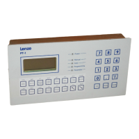
Provides a detailed diagram and description of the PT-1 terminal's physical components.
Explains the 4-line by 16-column LCD display and its operating modes.
Details the two areas of the PT-1 keyboard: Function and Numeric.
Details operation via Serial Interface X3 using PT-1 or Host Computer.
Describes manual control using external switches via Parallel Interface X1.
Explains program execution started/stopped by inputs (X1).
Details physical dimensions, mounting requirements, and ventilation considerations.
Details functions and pin assignments for Parallel Connector X1 (V5.XX software).
Details connections for an incremental encoder module FB-1 via Connector X4.
Details connections for an absolute encoder module FB-2 via Connector X4.
Details switches on the front panel for axis number selection and serial link.
Details DIP switches and jumpers on the motherboard for configuration.
Explains configuration options provided by Switch S3 for modes and hardware.
Lists jumpers used for selecting communication baudrate.
Explains jumper settings for pulse multiplication on incremental encoders.
Details jumper settings for Drive Enable and NC Ready active levels.
Covers encoder cable, inputs/outputs, analog signals, and general rules for protection.
Explains the three main parts: Setting Parameters, Programming, and Debugging.
Details Remote Control modes: Manual-Remote, Auto-Remote, and Test Mode.
Details Manual External mode for moving the drive with external switches.
Explains Automatic External mode for initiating sequences using I/O controls.
Details the required order for selecting Automatic, Remote, and Manual modes.
Details parameters related to Axis settings like program number, resolution, speed, and acceleration.
Lists axis parameters with their number, name, and a brief meaning.
Lists parameters for homing, acceleration, and positioning modes.
Explains how variables are declared and formatted.
Defines resolution (P1) and increments per revolution (P2) parameters.
Details parameters for Analog Voltage Ratio (P3), Scanning Rate (P4), Max Speed (P5), and Max Acceleration (P6).
Defines manual slow (P7) and fast (P8) jog speeds.
Sets software movement limits (P9, P10) and zero offset (P11).
Sets the sign for analog servo output (P12) and position feedback (P13).
Corrects for backlash in positive (P14) and negative (P15) directions.
Sets KV factors (P16, P17, P18) for position loop gain adjustment.
Sets switch point outputs (KP1, KP2) for gain factor changes (P19, P20).
Defines following error tolerance (P21) and in-position window (P22).
Details the six available methods for initializing the distance measuring system (Homing).
Defines the homing velocity parameter (P26).
Configures homing necessity (P27) and acceleration mode (P28).
Configures limit switch mode (P30), variable transmission (P31), and units per revolution (P32).
Defines variable name (P33), format (P34), lower limit (P35), and upper limit (P36).
Details initial steps for parameter entry: connecting PT-1 and checking mode.
Describes how the PT-1 checks entered values for validity and range.
Explains the structure of programs using main programs and nested subroutines.
Categorizes program instructions into Organisation, Motion-related, Wait, and Set.
Explains instructions like BEG, END, Label, and JMP.
Details jump instructions (JMP) and conditional jumps (IF) based on inputs and flags.
Explains conditional jumps based on Flags (IF Fvv) and Counters (IF Cvv).
Details conditional jumps based on variable values and absolute positioning.
Explains relative/absolute positioning instructions with or without program continuation.
Details positioning instructions with variables, and the STOP instruction.
Explains instructions for setting velocity (VEL) and acceleration (ACC) rates.
Explains deceleration (DEC) and WAIT instructions for timing and input conditions.
Details instructions for setting counters and performing variable arithmetic.
Explains the TXT instruction for displaying text and variable operations.
Details instructions for setting outputs based on inputs and flags using AND/OR logic.
Details instructions for setting flags using AND/OR logic with inputs and flags.
Explains instructions for variable arithmetic: add, subtract, multiply, divide, assign.
Details instructions for variable comparison jumps and position comparison jumps.
Explains instructions for saving variables, memory copy, and absolute positioning (DP).
Details PTP instructions for positioning with external touch probe signals and flags.
Explains PTP instructions, STOP, setting SOLLP, Vddd, and OVR.
Details initial steps for program entry: connecting PT-1, checking mode, and pressing PAR/KEY.
Explains loading programs from SX-1 and entering EDIT mode.
Describes completing entry, syntax check, saving programs, and entering EDIT mode.
Explains how to create a new program, including entering a program number.
Details erasing programs and listing stored programs in the SX-1.
Lists commands for handling instructions during programming: DELETE, INSERT, TEACH, LABEL.
Details variable data entry steps: PROG, selecting variables, and using MODE.
Describes running the main program defined by Parameter PO.
Explains using PT-1 to select and control programs in Automatic Remote Mode.
Details specific error codes, their meanings, causes, and remedies.
Lists error codes 11-30, their meanings, causes, and remedies.
Lists error codes 31-45, including those for interpolating mode.
Details a cut-off line application, including the program and variable usage.
Describes a transfer unit application involving drilling, with speed and error checking.
Describes a bottling/weighing machine application using a metering screw.
Describes a material transfer system with workstations and shortest path selection.
Details the key codes for accessing different parameter groups: None, 1000, 2000, 3333.
Lists programming instructions like BEG, END, HOME, VEL, ACC, JMP, WAIT, TXT.
Lists instructions for positioning (PA, PR), interpolation (LR), and touch probe (PTP).
Details instructions for setting flags, counters, and outputs using AND/OR logic.
Details conditional jump instructions based on variables and position values.
Summarizes menu operations: calling, selecting, entering, and working with items.
Details menu navigation for Run/Control and Parameter inspection.
Lists ECL commands grouped by key, with their meaning and memory usage.
| Brand | Lenze |
|---|---|
| Model | SX-1 |
| Category | Industrial Equipment |
| Language | English |