3. Product Overview UMX-TPS-TX100 series – User's Manual 24
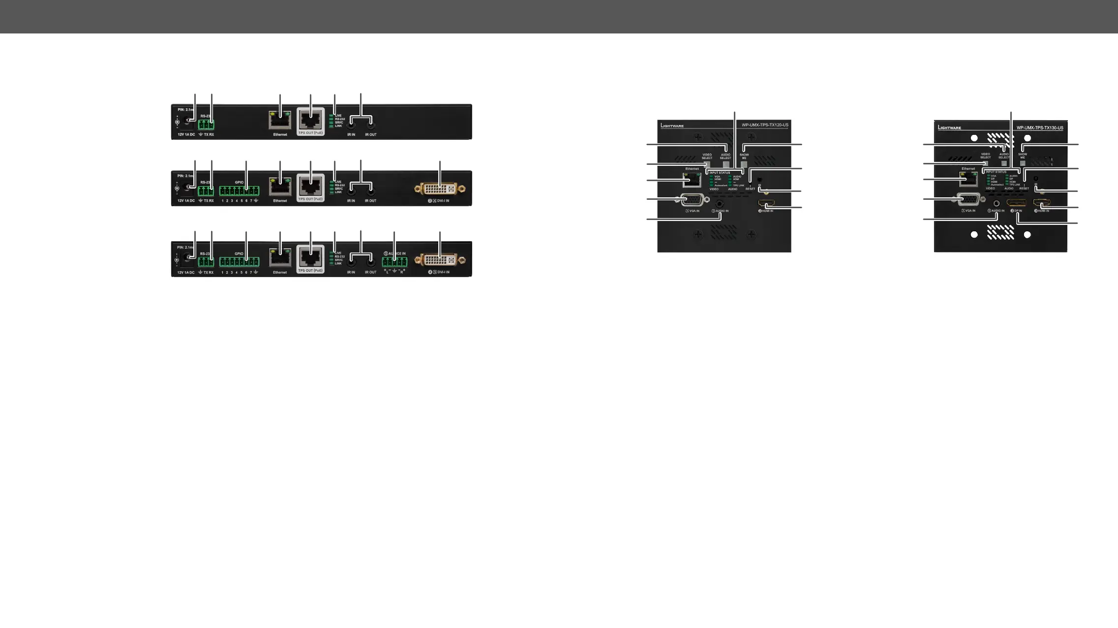
Rear View - UMX-TPS-TX100 series
UMX-TPS-TX120
UMX-TPS-TX130
UMX-TPS-TX140 /
UMX-TPS-TX140-Plus
1
12V DC input 12V DC input for local powering. For more details see the Locking 12V DC
Connection section or see all the available Powering Options.
2
RS-232
connector
3-pole Phoenix connector for controlling the device with LDC or third-party control
systems, or third-party device control. Pin assignment can be found in the RS-232
Connector section.
3
GPIO
assignment can be found in the section.
4
Ethernet
Controller (LDC), or upgrading it using Lightware Device Updater (LDU). Any third-
party control system can use this port to control the device.
5
TPS OUT
TM
signal transmission. Maximum CATx
cable distances can be found in the Maximum Extension Distances section.
6
Status LEDs The LEDs give feedback about the actual state of the device. See the details in the
Rear Panel LEDs section.
7
IR IN and
OUT
receiver (IR IN) and transmitter (IR OUT) connection. Pin assignments can be
found in the IR Connector section.
8
Audio2 input 5-pole Phoenix connector for balanced analog audio input. Pin assignment can
be found in the Analog Stereo Audio (Phoenix) section.
9
DVI-I input
the DVI-I Connector section.
2
7
4 5 6
1
2 3
7
9
4
5 6
1
2 3
7
8 9
4
5 6
1
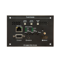
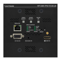
Front View - WP-UMX-TPS-TX100 series
WP-UMX-TPS-TX120-US WP-UMX-TPS-TX130-US / WP-UMX-TPS-TX130-US-Plus
1
Input Status LEDs LEDs give feedback about the current status of the unit and input signals.
See the details in the Front Panel LEDs section.
2
Audio Select button Button for switching between audio sources. See the details in the Audio
Select Button section.
3
Video Select button Button for switching between video sources. See the details in the Video
Select Button section.
4
Ethernet
Device Controller (LDC), or upgrading it using Lightware Device Updater
(LDU). Any third-party control system can use this port to control the
device.
5
VGA input D-SUB connector for analog video signal.
6
Audio input
7
Show Me button
(bootload) mode, DHCP settings, restore factory default settings,
condition launching in Event Manager).
8
Reset button Pushing the button reboots the unit.
9
IR detector IR Detector can sense IR light which can be forwarded to the receiver
side or use for controlling functions.
q
HDMI connector for DVI video or HDMI video and audio.
w
DisplayPort input
1
3
4
5
2 7
8
9
6
q
1
3
4
5
2 7
8
9
6
w
q
 Loading...