5. Software Control - Lightware Device Controller UMX-TPS-TX100 series – User's Manual 53
RS-232 Recognizer
Example.
The signal presence triggers a bi-directional communication with the VC codec via RS-232:
Step 1. Turn on the recognizer: Enable it on the P1 serial port.
Step 2. Set the delimiter (in hex format). In this case, the
delimiter character is ':', which is '3a' in hex format.
serial data, the serial message is stored in string (in Rx
and ActiveRx property), hex (in RxHex and ActiveHex
property) and hash (in Hash and ActiveHash property) format. These stored content can be set as a
condition in the event manager.
INFO: The stored content is the incoming data which arrives before the delimiter or between the two
delimiters.
Step 3. Set the Active timeout 100. This property is responsible for erasing the temporary storage (ActiveRx,
ActiveRxHex, ActiveHash) after the elapsing time. In the below example, it can be seen how does the
recognizer properties change during the communication:
Î UMX-TPS-TX140-Plus: PING
Rx ActiveRx
Í VC codec: Login:
Rx ActiveRx
Login: 4C6F67696E3A 2D8A5E38 Login: 4C6F67696E3A 2D8A5E38
Î UMX-TPS-TX140-Plus: Admin
Rx ActiveRx
Login: 4C6F67696E3A 2D8A5E38
Í VC codec: Password:
Rx ActiveRx
Password: 50617373776F72643A 79059B26 Password: 50617373776F72643A 79059B26
Î UMX-TPS-TX140-Plus: Admin
Rx ActiveRx
Password: 50617373776F72643A 79059B26
: Login name : ...
Delimiter (hex format: 3A)
Stored string
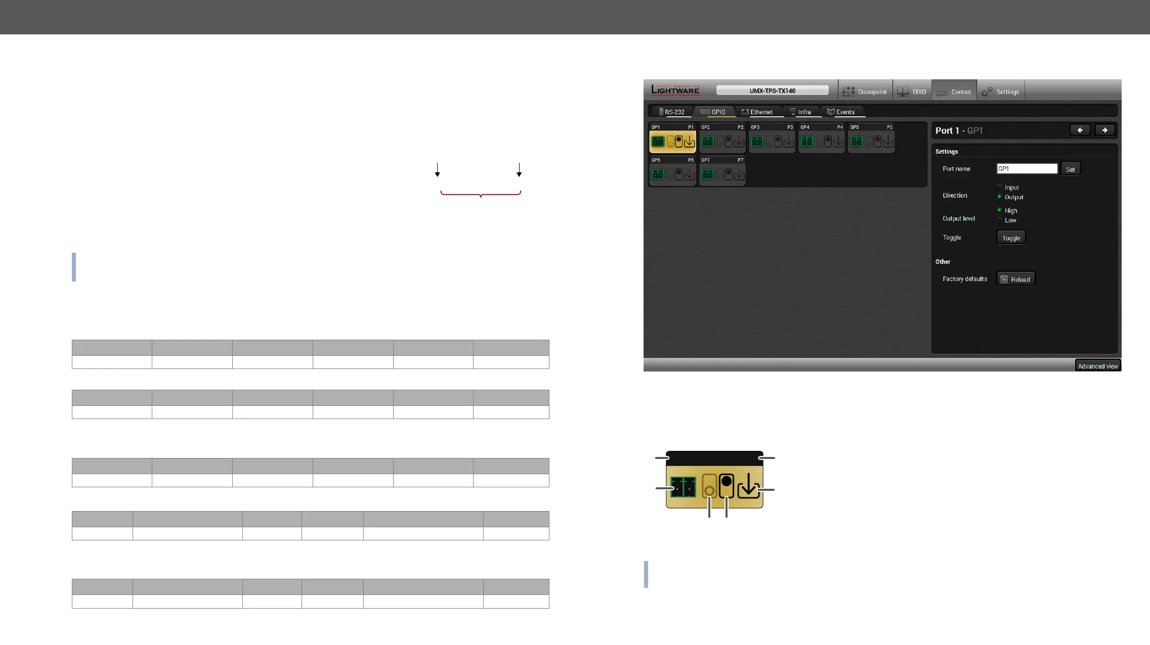
GPIO Tab
GPIO tab in Control menu
The GPIO port has 7 pins, which operate at TTL digital signal levels and can be controlled by LDC or protocol
commands. Select a GPIO pin and under the Port settings section; the settings (pin direction and input level)
are displayed on the port tiles as well:
1
GPIO pin name
4
High level indicator *
2
GPIO port icon
5
Pin direction:
Input: down arrow
Output: up arrow
3
Low level indicator
6
GPIO port number
* Highlighted with black means the current setting.
INFO: Output level can be set only in case of setting the pin direction to Output. In case of input direction
the output level setting and the Toggle button is not available.
For more details about GPIO interface see the GPIO Interface section.
GP1 P1
5
 Loading...