3. Product Overview UMX-TPS-TX100 series – User's Manual 26
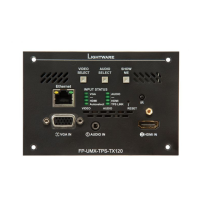
Rear View - FP-UMX-TPS-TX100 series
1
TPS output
TM
signal
transmission. Maximum CATx cable distances
can be found in the Maximum Extension
Distances section.
2
RS-232
connector
3-pole Phoenix connector for controlling the
device with LDC or third-party control systems,
or third-party device control. Pin assignment
can be found in the RS-232 Connector section.
3
48V DC
input
Power the device remotely by a PoE-compatible
power injector (TPS-PI-1P1). If the device has
to be powered by a local adaptor (PSU-48VP1),
connect the output to the 2-pole Phoenix
more details about powering options in the
48V DC Connection section or see all the
available Powering Options.
1 2
3
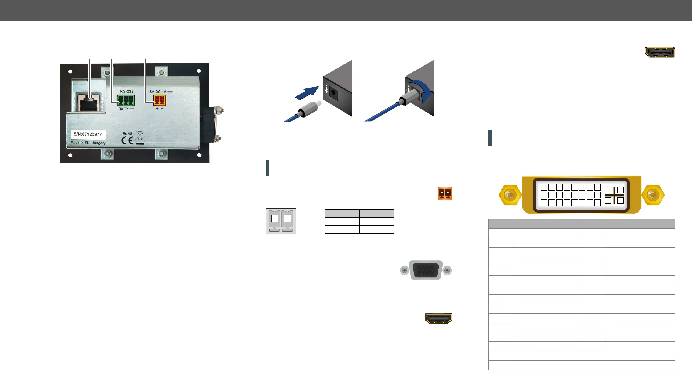
Electrical Connections
Locking 12V DC Connection
Locking DC connector
UMX-TPS-TX100 series transmitters are built with locking 12V DC
connector. Do not forget to turn the plug clockwise direction before
disconnecting the power adaptor.
WARNING! Always use the supplied 12V power adaptor. Warranty
void if damage occurs due to use of a different power source.
48V DC Connection
2-pole Phoenix connector for 48V DC 1A power connection.
Pin nr. Signal
1 +
2 -
2-pole Phoenix connector and plug pin assignments
VGA Connector
The transmitter provides a standard 15-pole
D-SUB female connector for connecting VGA
devices. Always use high-quality VGA cable for
connecting sources and displays; using a VGA cable where all the pins
are wired (including the DDC channel's wires) is highly recommended.
The extender provides standard 19 pole HDMI connector
for input. Always use high quality HDMI cable for
connecting sources and displays.
12V
1A
DC
12V
1A
DC
PIN: 2.1mm
PIN: 2.1mm
21
DisplayPort Connector
provide standard 20-pole DisplayPort connector for input. Always use
high quality DP cable for connecting DisplayPort devices.
DVI-I Connector
UMX-TPS-TX130, UMX-TPS-TX140, and UMX-TPS-TX140-Plus
transmitters provide a standard 29-pole DVI-I connector for input
where digital and analog pins are connected internally. Hence users
can use the connector receiving DVI-A (analog video) and DVI-D
signals (digital video and digital audio) as well.
ATTENTION! Only one (DVI-A or DVI-D) mode is available at a time.
You can use the Video Select button to choose the input source.
Always use high quality DVI cable for connecting DVI devices.
The following drawing and table show the pinout of DVI-I connector
and the position of analog and digital signal pins.
Pin Signal Pin Signal
1 TMDS Data2- 16 Hot Plug Detect
2 TMDS Data2+ 17 TMDS Data0-
3 TMDS Data2 Shield 18 TMDS Data0+
4 not connected 19 TMDS Data0 Shield
5 not connected 20 not connected
6 DDC Clock 21 not connected
7 DDC Data 22 TMDS Clock Shield
8 Analog Vertical Sync 23 TMDS Clock+
9 TMDS Data1- 24 TMDS Clock-
10 TMDS Data1+ C1 Analog Red
11 TMDS Data1 Shield C2 Analog Green
12 not connected C3 Analog Blue
13 not connected C4 Analog Horizontal Sync
14 +5V Power C5 GND
15 GND (for +5V)
1 2 3 4 5 6 7 8
9 10 11 12 13 14 15 16
C1 C2
C4C3
C5
17 18 19 20 21 22 23 24
 Loading...